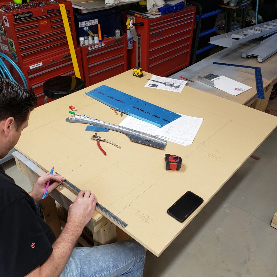
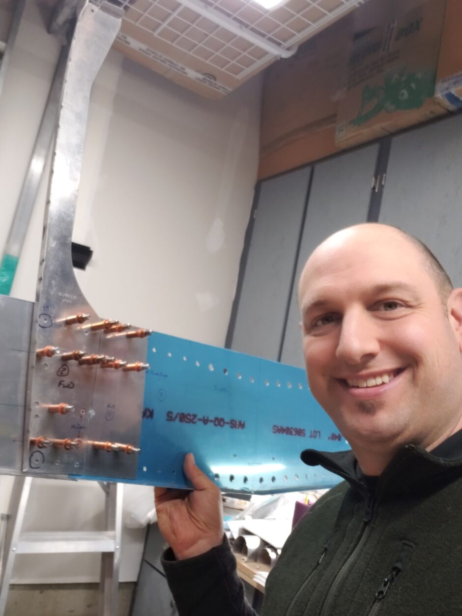
I’m back and ready to tackle this F-404 bulkhead with a new approach. My last attempt ended in much frustration due to a few aspects. One of which was the misleading dimensions given in the instructions, and the other was using a jig board that was not sufficiently large enough to hold the entire assembly. And finally, my secret weapon. I had my buddy Garet come over to help me with getting super accurate measurements. When it comes to precision…he’s the best!
Also note that the building that took place in this one post actually took place during several build sessions. I chose to make one long post to help readers see the entire process of the forward bulkhead assembly.
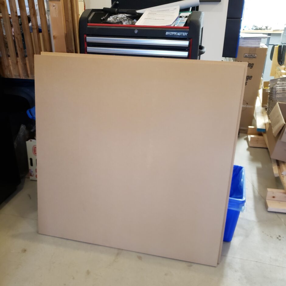
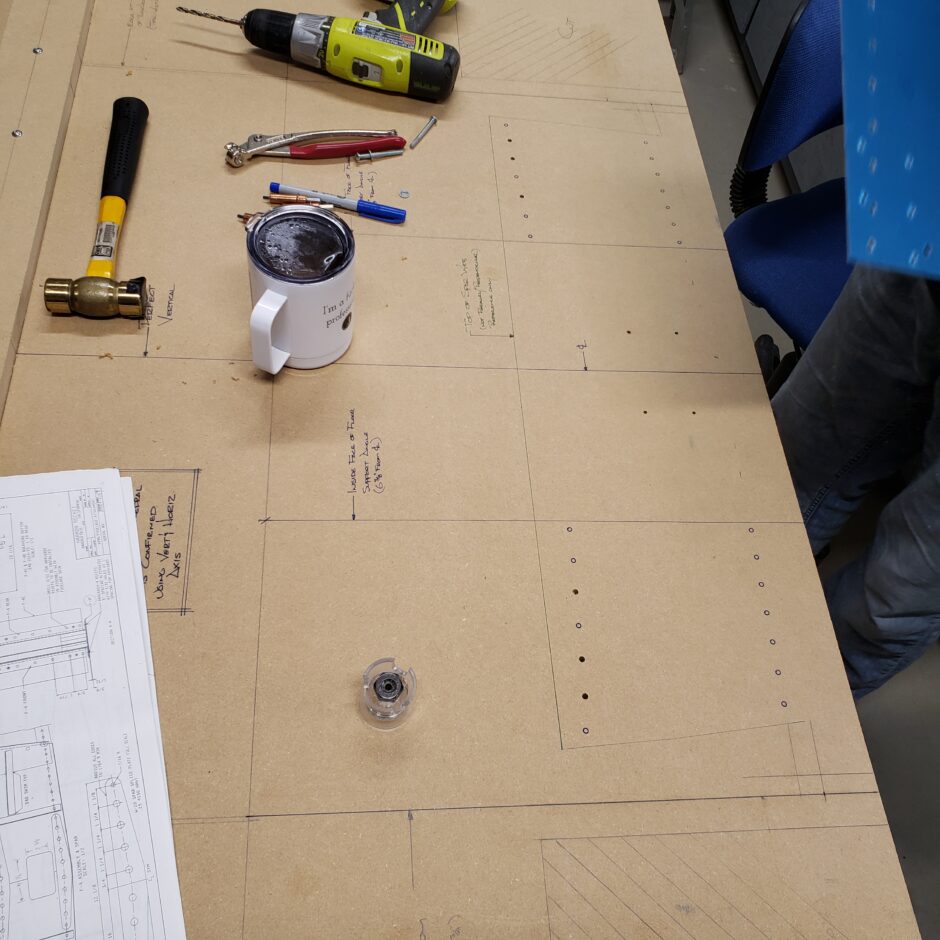
Begin with laying out a perfect vertical centerline. This is important because all lateral dimensions are taken from here. The centerline needs to be made on both the jig board and down the center of the front bulkhead spar web (F-404C). We also used the rectangle cutout pilot holes to use clecos to hold the spar web to the jig. The good thing about using MDF board is that is works really well for using clecos.
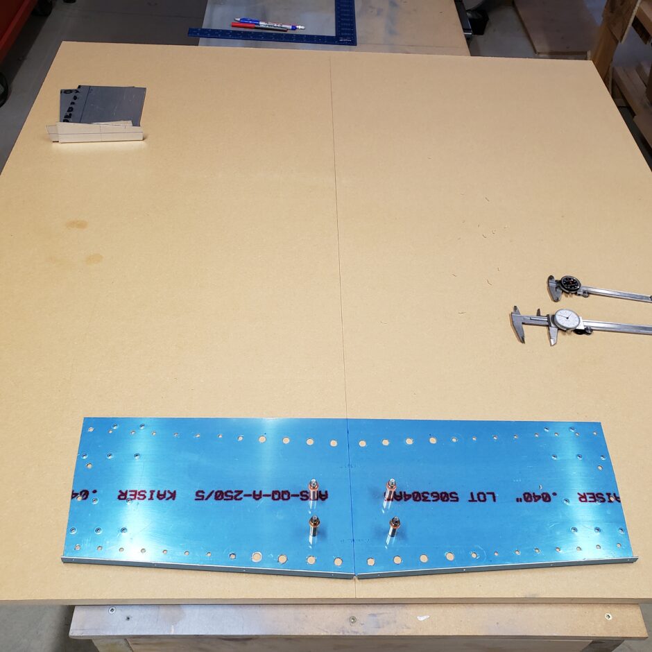
We extended the lower flange lines outward. This is the lines that the “filler pieces” need to align with. We also made outer vertical lines that were perfectly vertical to the centerline. These are the outter most dimension of the lower side of the forward side of the bulkhead (30 3/4″)
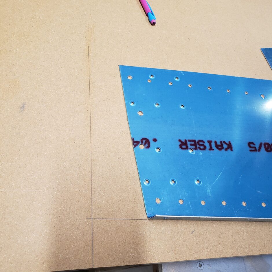
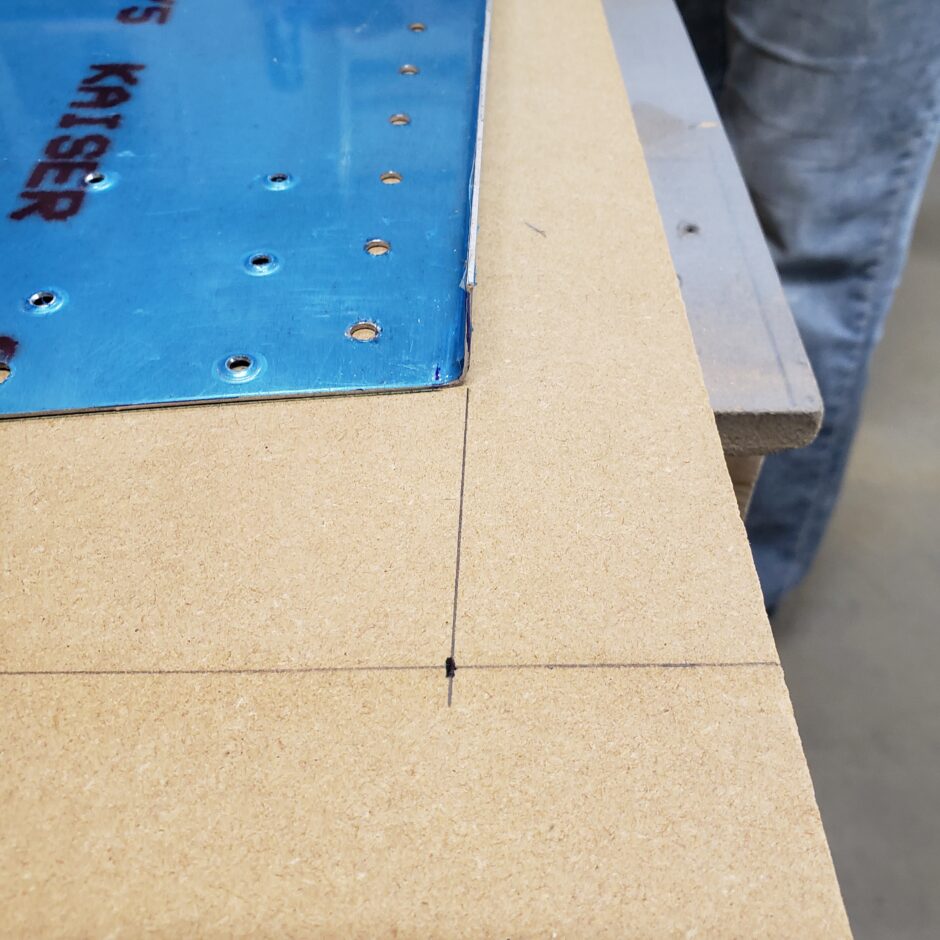
Lots of measuring…make sure that all measurements are taken from the centerline and horizontal line. Evenly on both sides to ensure symmetry with the outer dimension of the bulkhead.
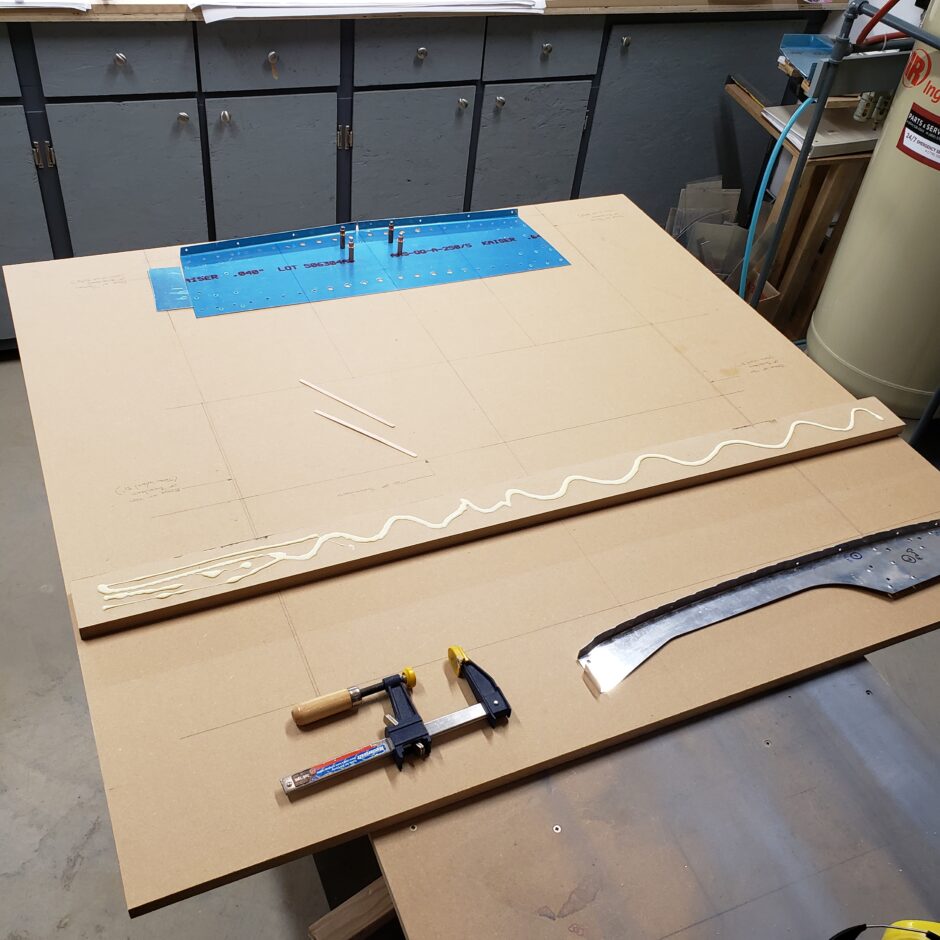
To provide a solid perfect horizontal dimension for the upper ends of the bulkhead uprights (F-404A-R / F-404A-L) we cut a strip off the top of the jig board and will glue & screw it to the board. The other reason that this is useful is to provide a clamping surface to help hold the upright formers at the proper dimension until they can be match-drilled to the spar web plate.
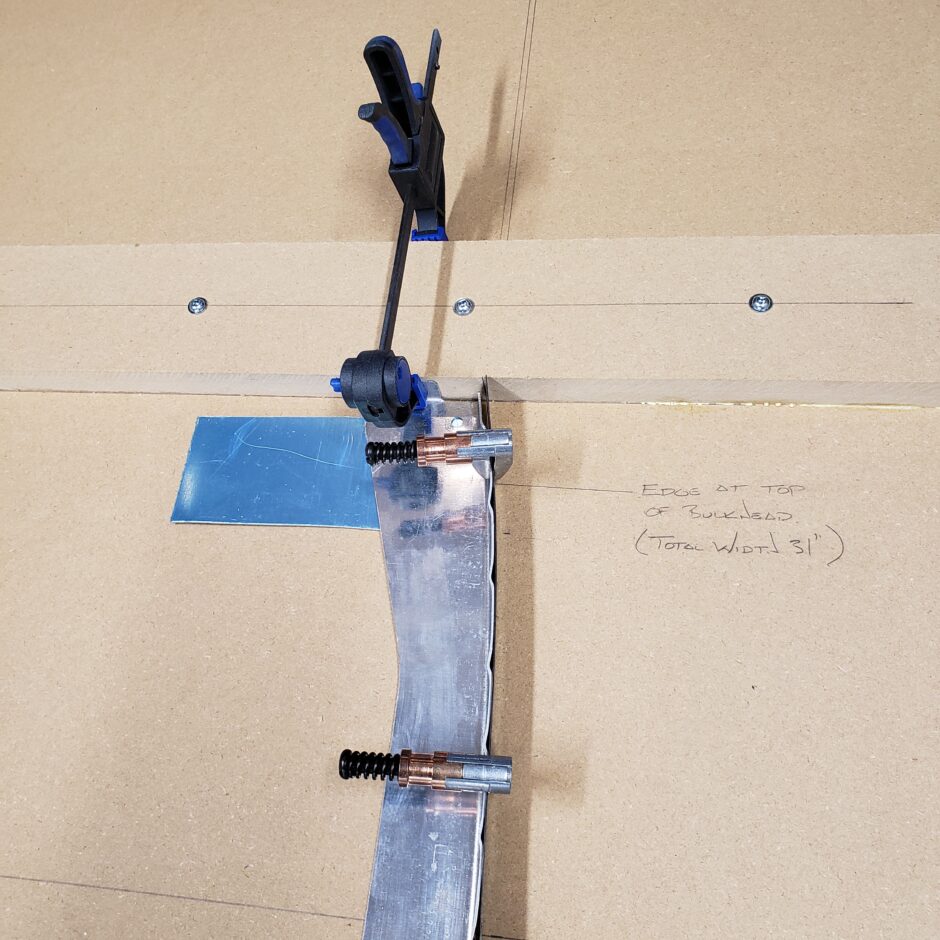
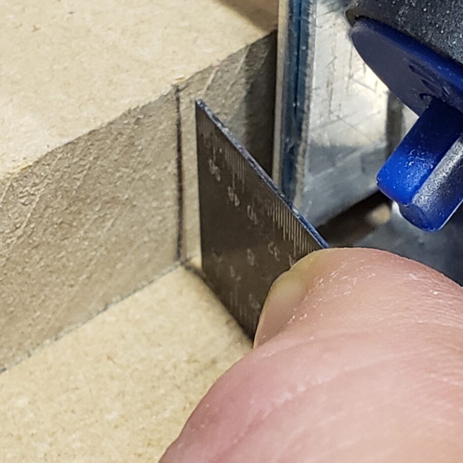
To help establish the correct top dimension (width) of the uprights, we used the reference dimension lines drawn on the jig board, then clamped them in place along the clamping board. We also used a steel ruler to find the true outter dimension, as the top of the upright is formed / stepped down to allow a mating part sit flush. Therefore, using the ruler we could find the true outter edges.
Slowly, we are getting the forward side of the bulkhead aligned…very, very slowly.
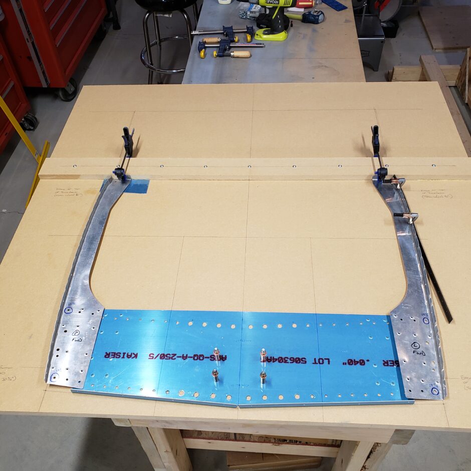
In the picture below, you can see that we match-drilled several of the predrilled spar rivet holes. This will help to keep the spar web flange perfectly aligned.
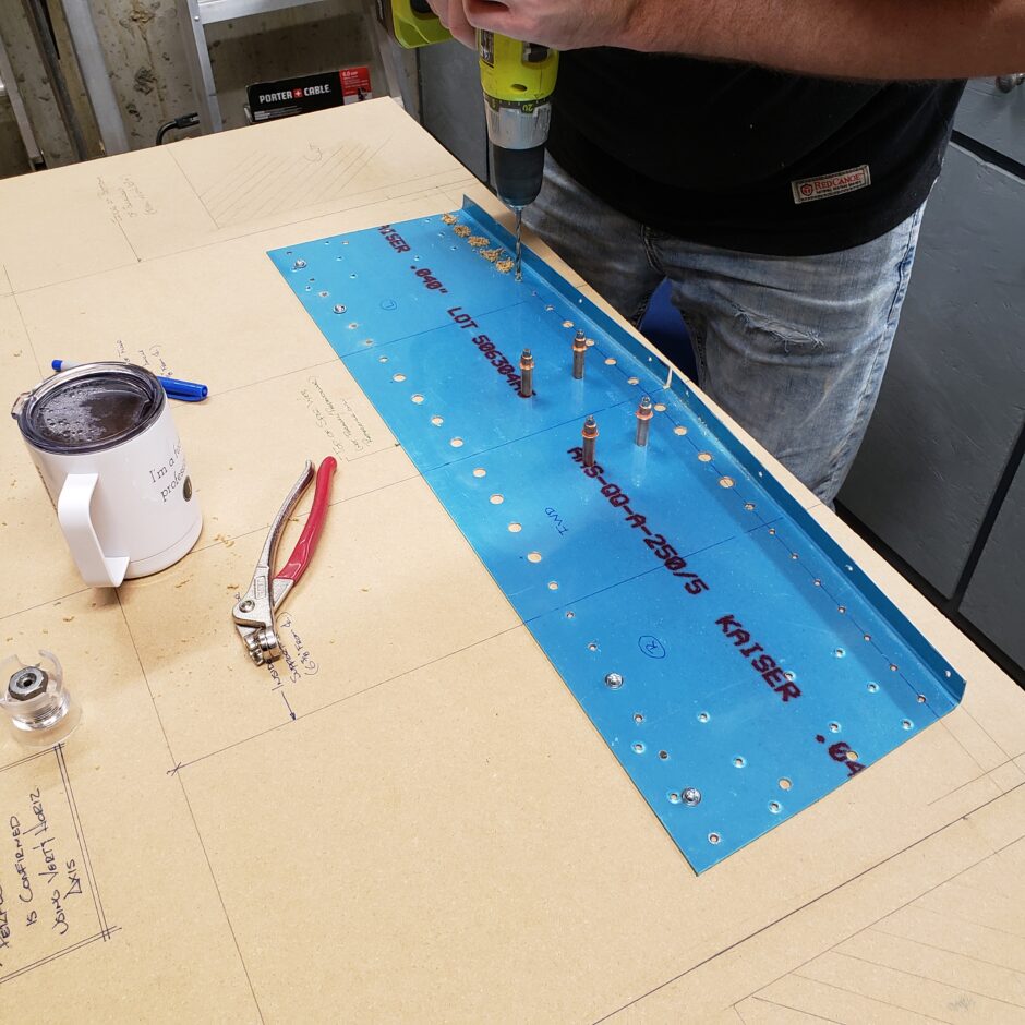
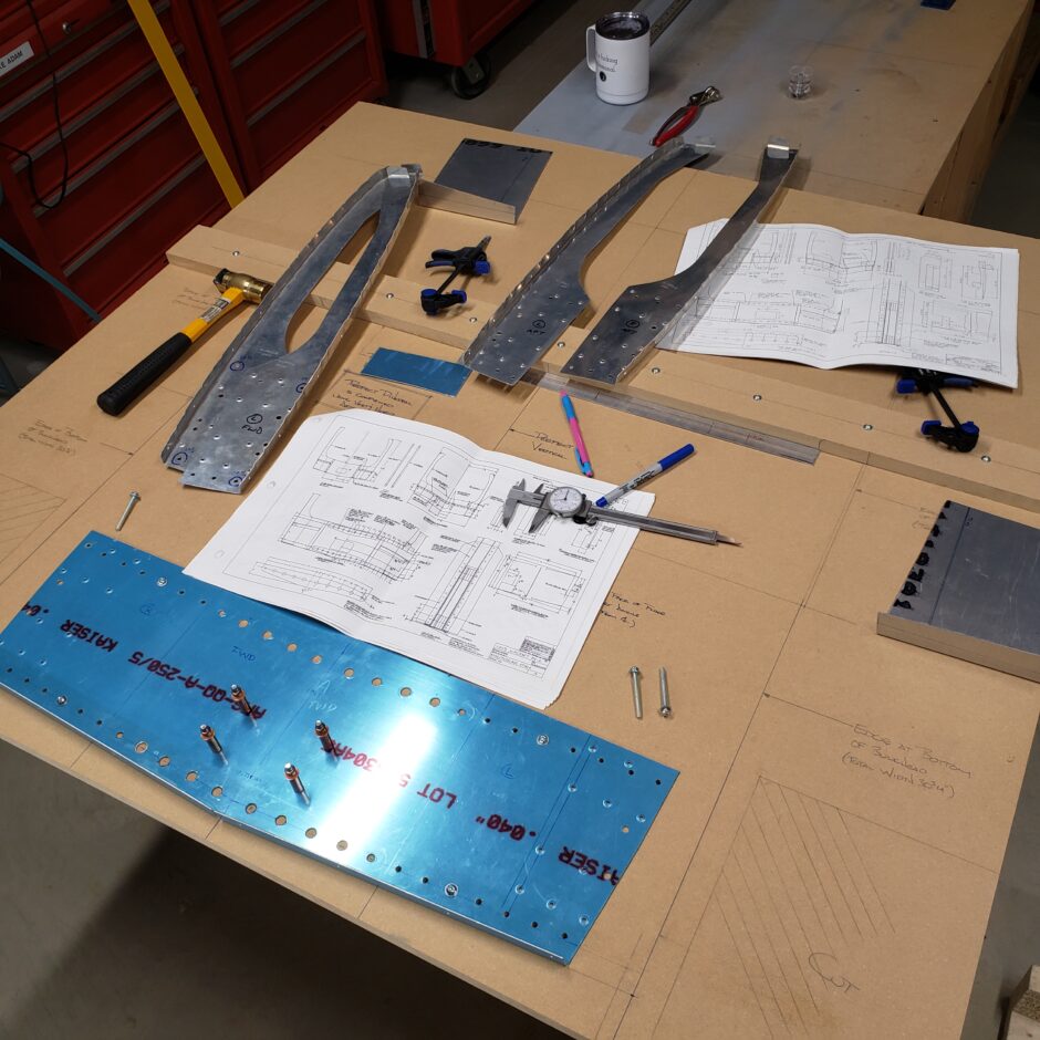
Now to stop and confirm that our meaurements are correct up to this point. To test and check, we mounted the wing spars to the jig board and mounted the spar web plate to the spar. From here we were able to check that we have the same vertical dimensions on either side from the horizontal plane (measuring dihedral). Good news, both sides were even!
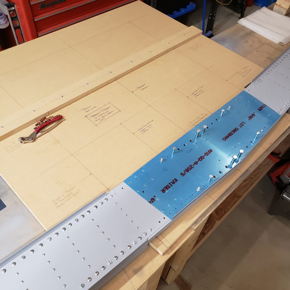
Perfect alignment with all the bolt holes.
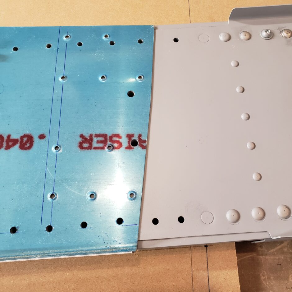
Below is also a test fit of the vertical former. As you can see, the clearance (gap) between the upright flange and the forward spar web doubler flanges (upper and lower) are as advertised in the plans. Also note, that the lower corner of the jig has been cut out to allow the spar assembly to fit without interference.
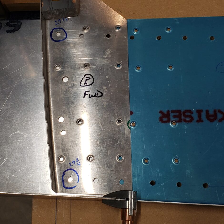
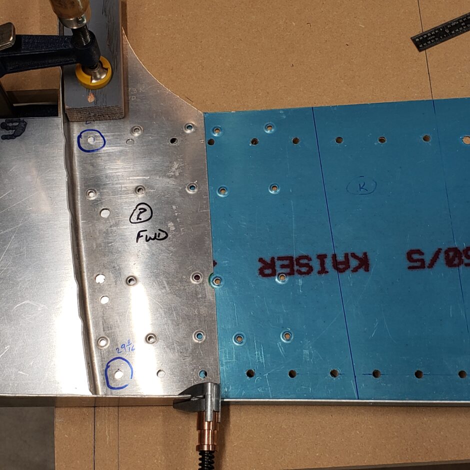
Another item to note in the image below and the next few images is the pre-punched hole identified as per the F1 Aircraft plan notes.
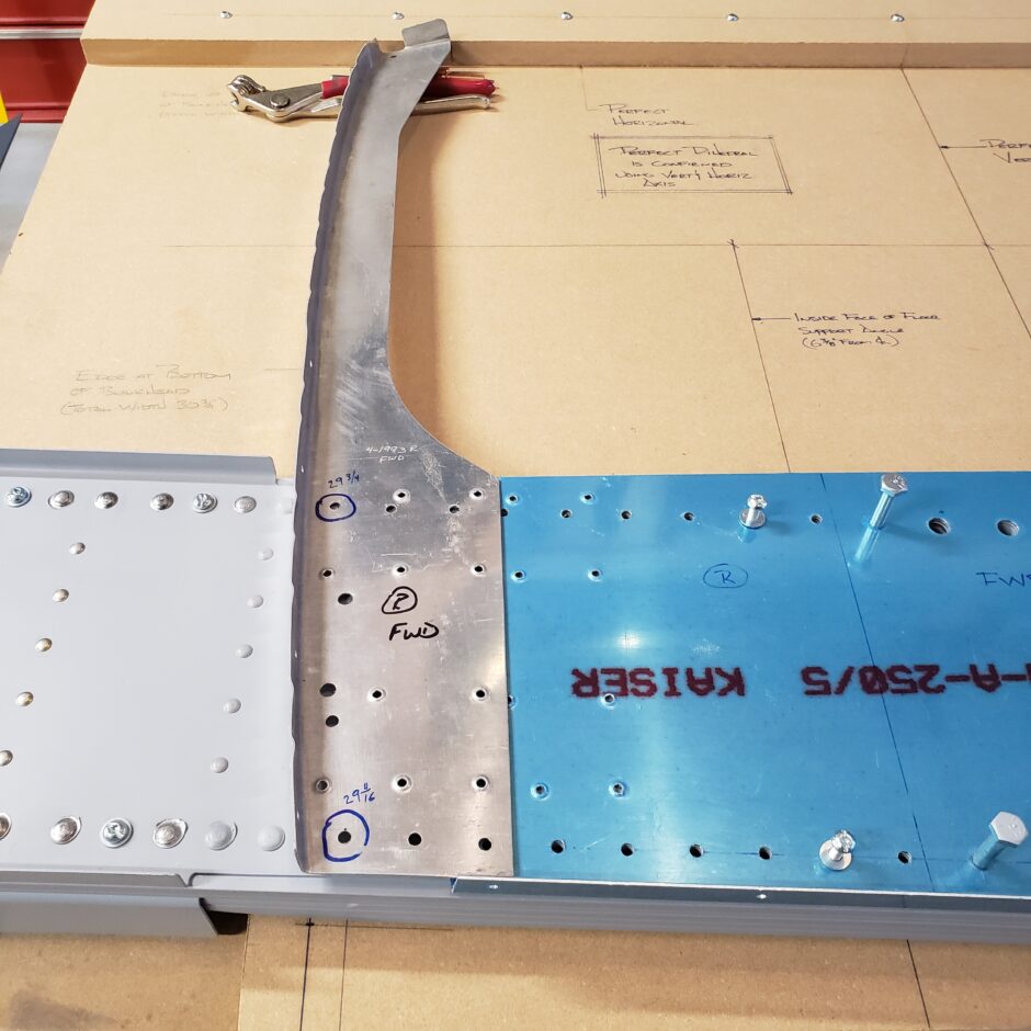
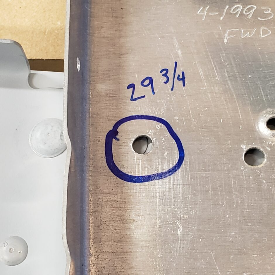
As you can see, in the image below, the upper PP hole identified as 29 3/4 inch – does not align with anything on the spar other than the double flush rivet below the vertical former.
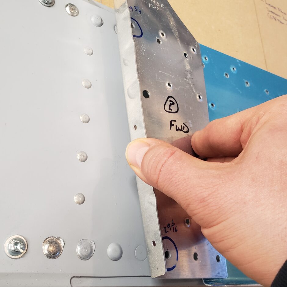
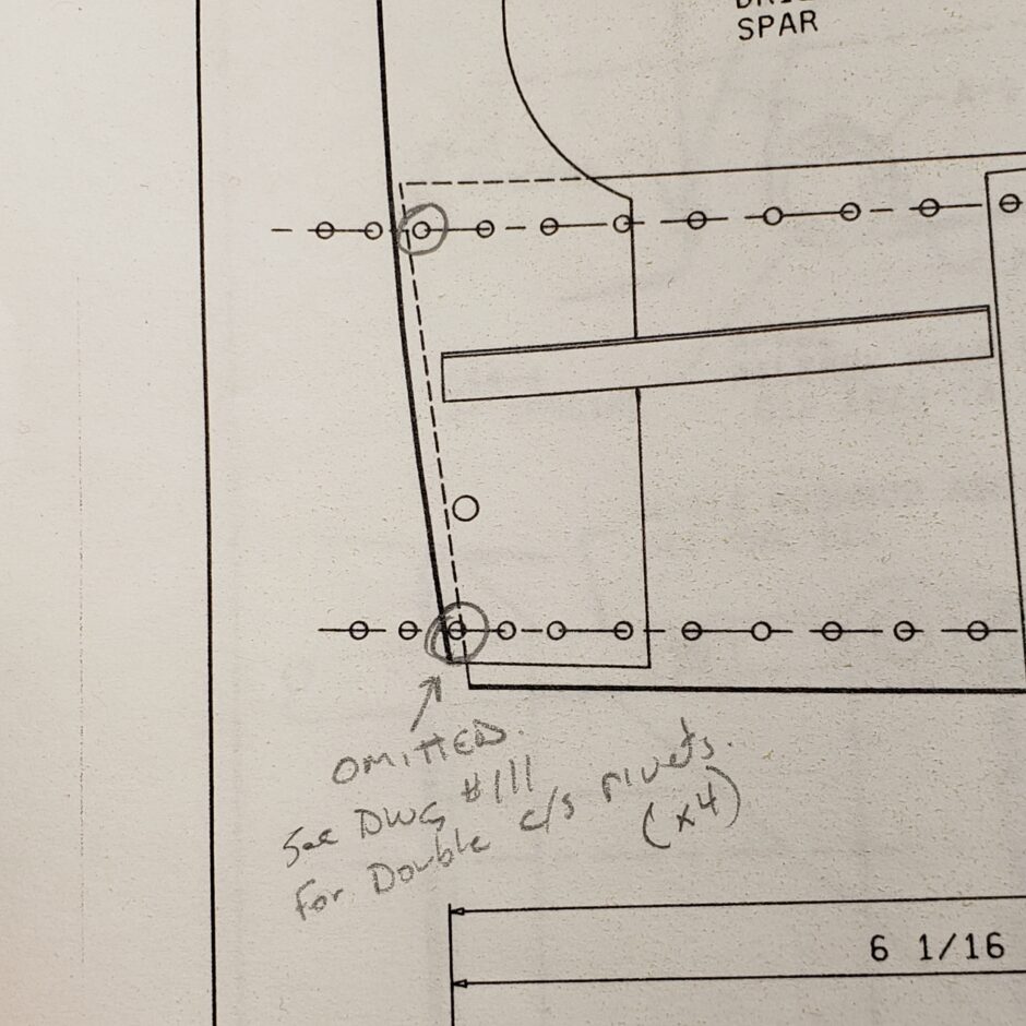
In the image below, you can more clearly see the double flush rivets, which are in place to allow the forward side of the bulkhead to fit flush and flat against the forward side of the spar.
Speaking of the double flush rivets, here is a picture of my plans where I’ve added a note regarding the countersunk rivets. This is one of the Blueprint Notes provided by Vinces Rocket.
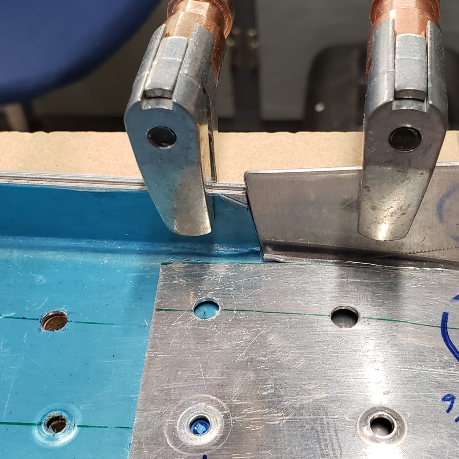
The image below is a close up of the spar web plate (blue on left), the filler extension plate (larger untrimmed flange on the right side) and the vertical bulkhead former laid over top. What is hard to see is that clamped to the rear side of the lower flange is a piece of scrap angle used to hold the flange in alignment.
Now I set the lower outer edges of the uprights. Note the blue measurement line drawn on the jig board near the lower left corner. As the extension flange lies over top, this line needs to be accurately transferred to the upper surface of the flange. Once set, I clamped the upright flange to the jig board.
Also note how the inboard edge of the F-404A-R former interferes with one of the RV-4 pre-drilled and dimpled holes in the spar web plate. You can see that I maked a trim line around this hole to provide some clearance. It was the only solution I could come up with.
In the image below, you can see that I trimmed the flange to provide clearance for the dimpled hole on the spar web plate.
With the F-404A-R former in place, the next step was to add a doubler plate. The purpose of this plate is to provide a riveting surface for the main doubler that will cover both the F-404A-R former and the doubler plate, while also attaching the spar web and spar web extension (below F-404A-R). There are no dimensions given for this doubler. I basically went by pictures provided by other builders and counting bolt holes from the center of the spar web outward. Once I found the approximate size of the doubler plate, I made it large enough to run evenly between the appropriate bolt holes.
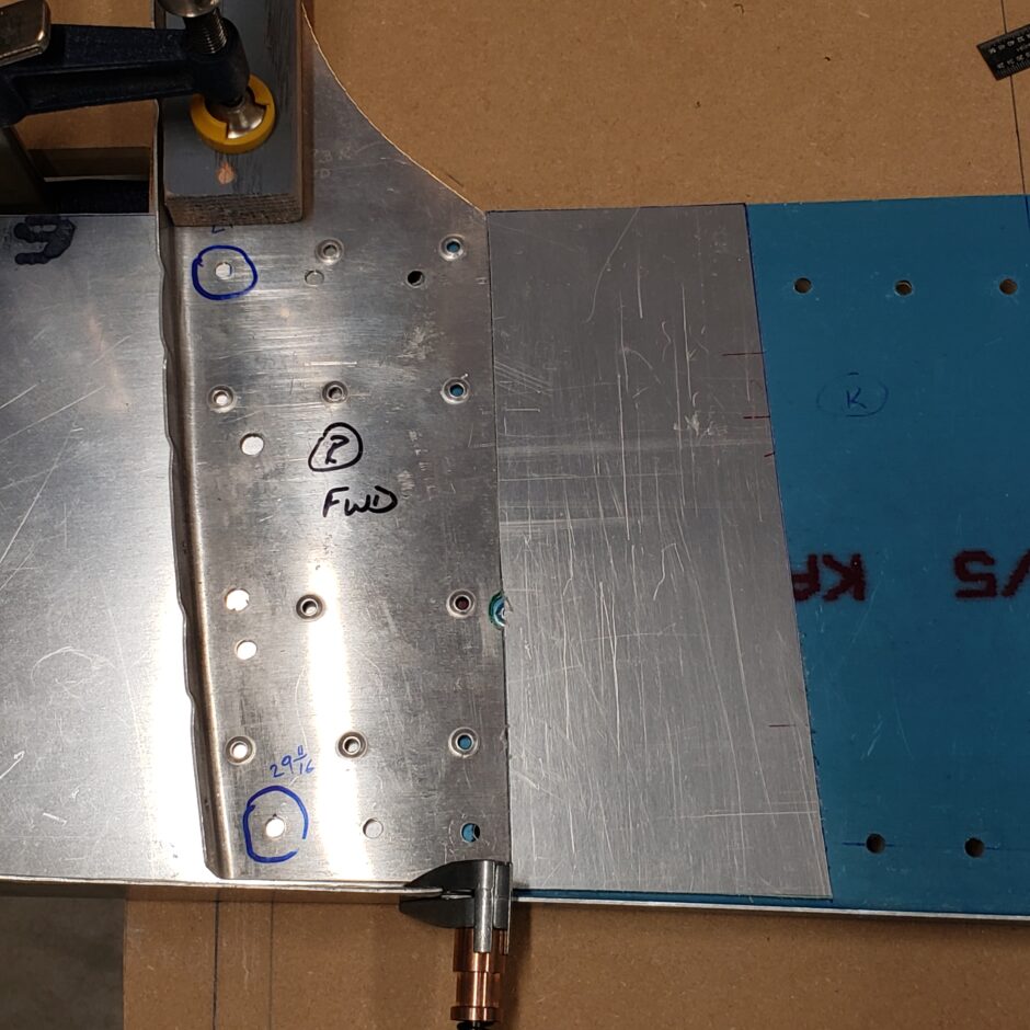
As you’ll start to notice, there are a LOT of rivets needed in this assembly. Where possible, existing holes are used. This requires a bit of thought, flipping parts over, and avoiding the edges of the various parts. As you can see, the rivet layout will NOT be beautifully laid out and a symmetrical work of art. This is totally acceptable. This modification doesn’t have to be beautiful, it needs to be functional because it won’t be seen once installed in the plane.
Another important thing to identify at this point is where the floor board support angle attaches. You can see this line of rivets identified below. The dimension given on the HRII plans is 5 1/8″ and Vince’s Blueprint Notes have a correction to this dimension showing that it should be 5 1/2″. Also note that the front and rear halfs of the bulkhead are not the same. Be sure to put the angles in the correct place on each half.
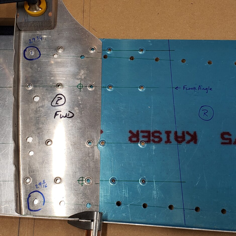
In the picture below, you can see how the rivet layout is progressing. I am also starting to fit in additional rivets here and there where spacing allows. There are also some pre-drilled holes that you just have to work around that will give you no edge distance. These are also identified.
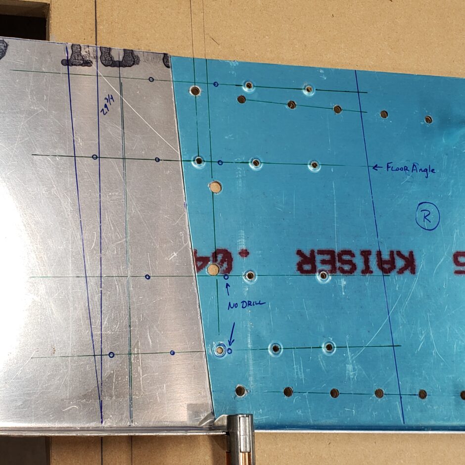
With the F-404A-R upright in place, you can see where I had to extend the rivet lines to be able to keep thing aligned as the layers are built up.
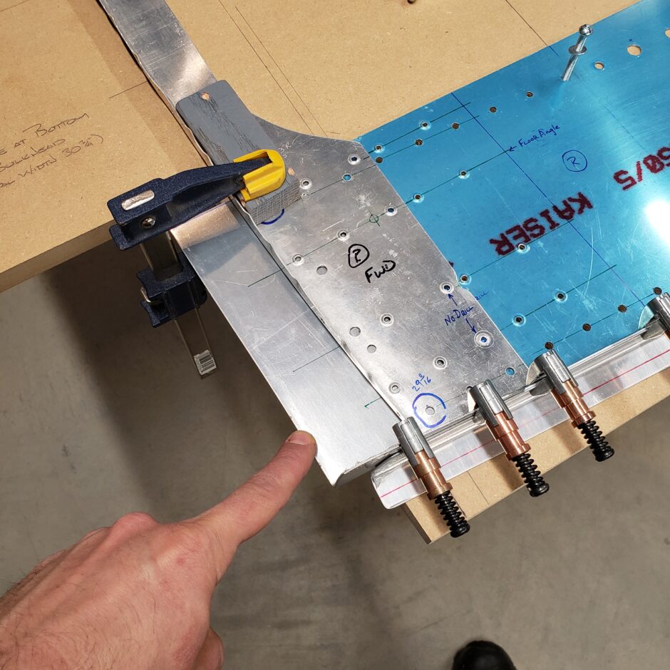
As I’m getting close to drilling some pilot holes, I make one last check of the upper and lower outer dimensions for the bulkhead. The first picture is checking the upper vertical arm for alignment and the second picture is the lower side of the frame.

Drilling
Time to start drilling. It’s nice to be able to add clecos to start holding the parts in place. One of the tricks that I used with great success in the coming steps is using the jig board as a drill jig as well. Once I had all the parts clamped in place, I started by drilling the pre-punched holes. I drilled all rivet holes all the way through the jig board. The reason for this is later, when you get to putting the big doubler plate over top all these parts, you won’t be able to see any of the rivet holes. Therefore, by using the jig board to back drill, you’ll ensure the best accuracy you can get when transferring the holes.
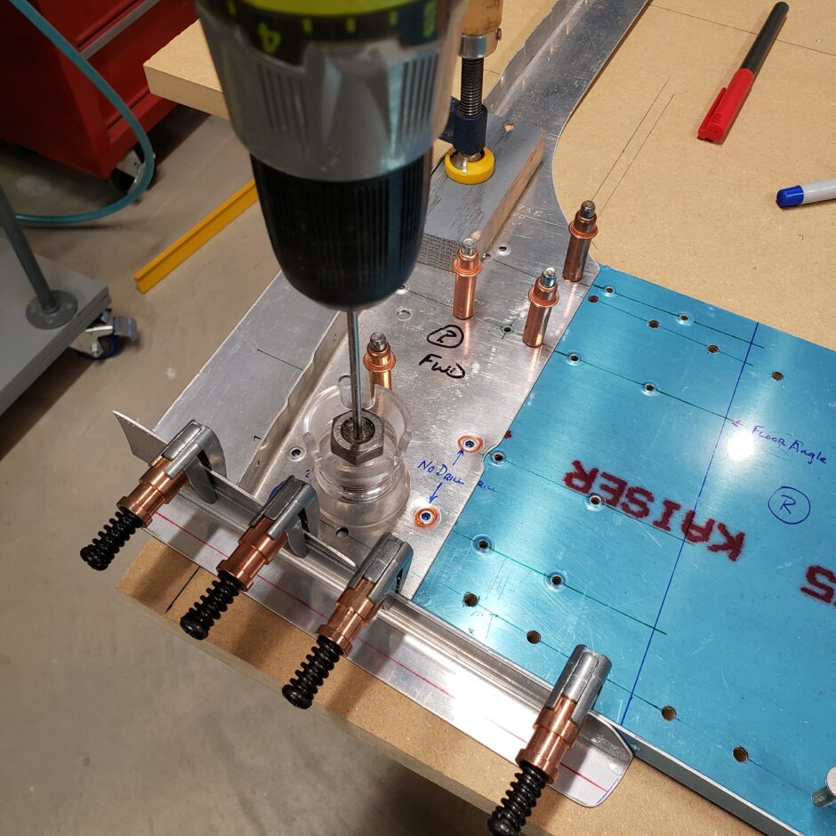
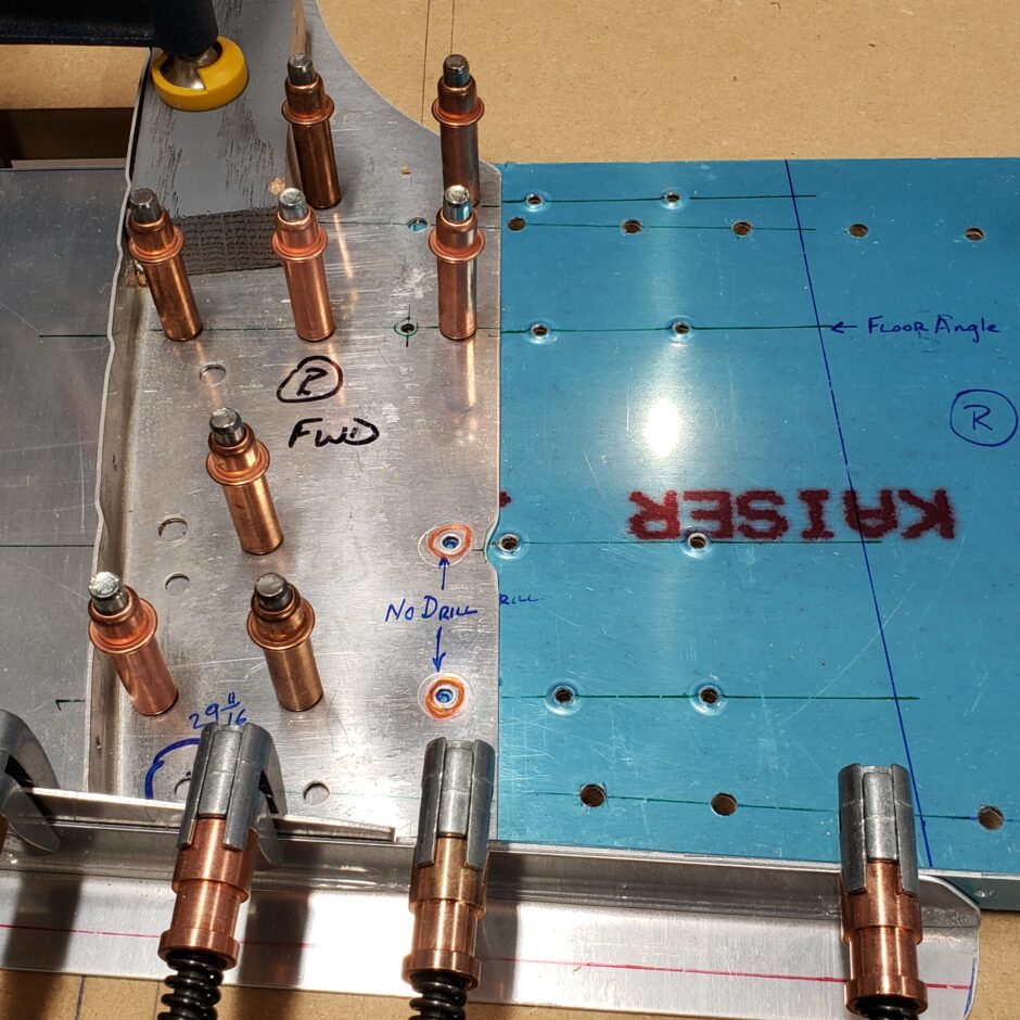
After drilling the F-404A-R former to the spar web and spar web extension, the next step was to add the filler plate. The filler plate was drilled from the pre-punched holes on the aft side of the assembly. Remember how I drilled all the way through the jig board, this is why. It’s super easy to now transfer the holes to the new undrilled part.
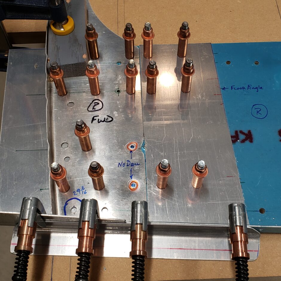
One big step forward!! A little bit of visual progress.
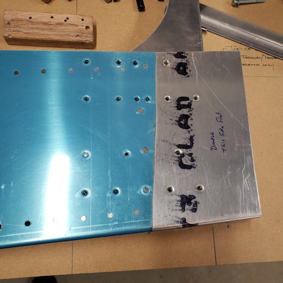
Here is a shot of the flip side. As you can see, you really need to be careful about maintaining edge distance of the holes being drilled, not just with the predrilled hole but also with the edges of the material.
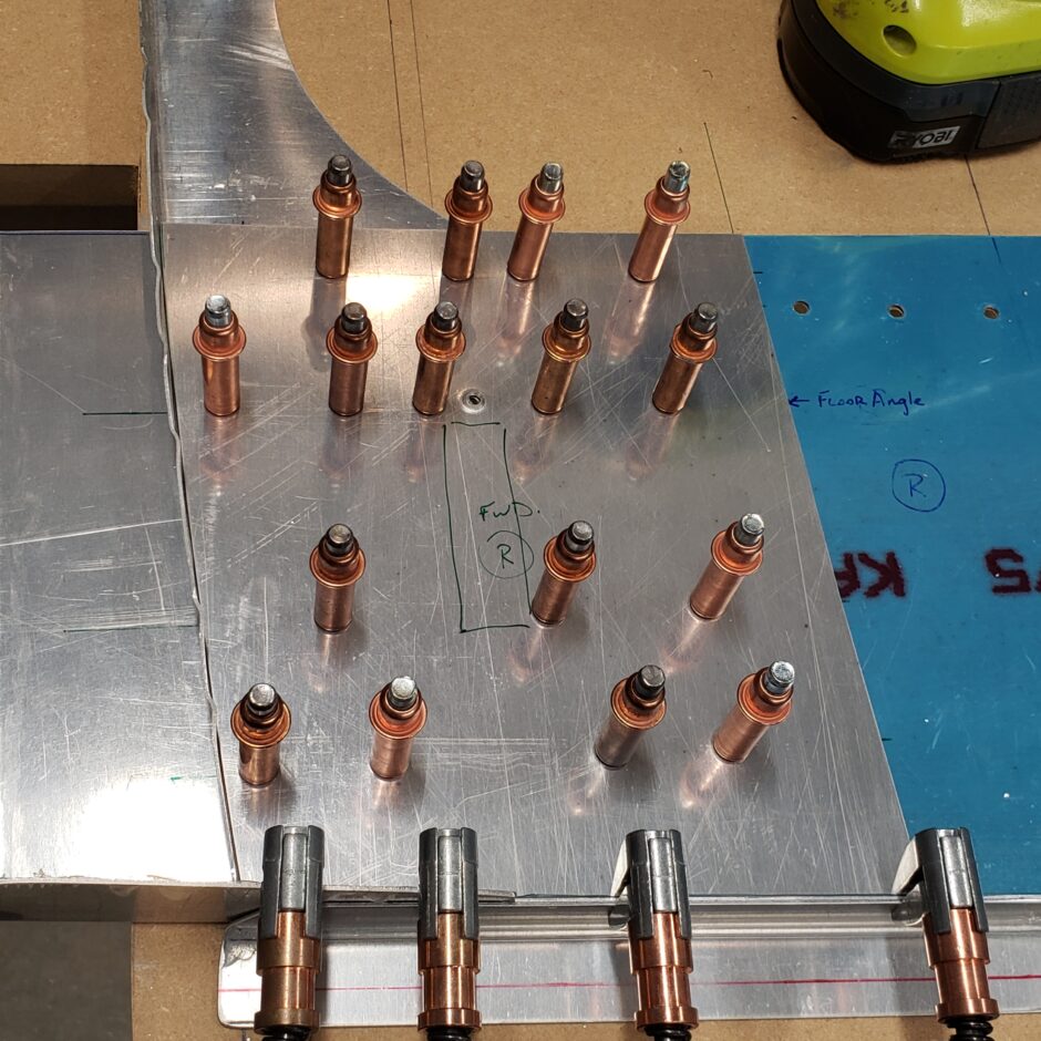
Now it’s time to add the big doubler plate. As it’s still oversized, I had to remove the F-404A-R frame to be able to get it clamped and drilled. Again, this will be all back drilled from the bottom up. Before drilling make sure it’s clamped down good and tight.

In the next photo, I’ve progressed a bit further along. The big doubler plate has been drilled, and the oversize edge has been trimmed to match the inner radius of the F-404A-R frame. I have also identified an area (outlined by rectangle) where there are 2 bolt holes that need to be match drilled to the spar. I did this so that I wouldn’t add any additional rivets in the area that would interfere.
In the image below, you can see I have added a bunch of additional rivet locations in keeping with the original spacing patter as best I could. I also used pictures from other builders to add the extra rivet rows. The HRII plans have a few details about the rivet spacing, but it’s not a huge amount of help in determining the layout pattern.
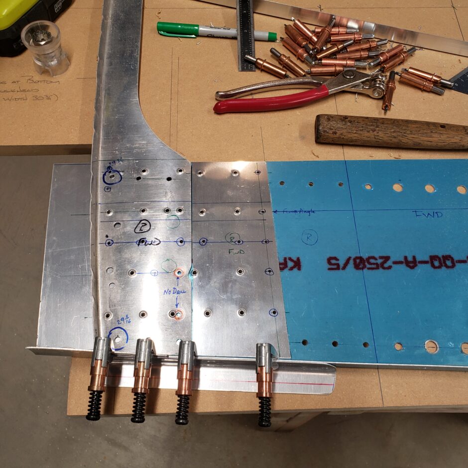
Again, all the holes were drilled through the jig board, then the big doubler plate was clecoed and clamped in place using some of the pre-drilled holes. Then I back drilled the remainder of the new additional rivet holes.
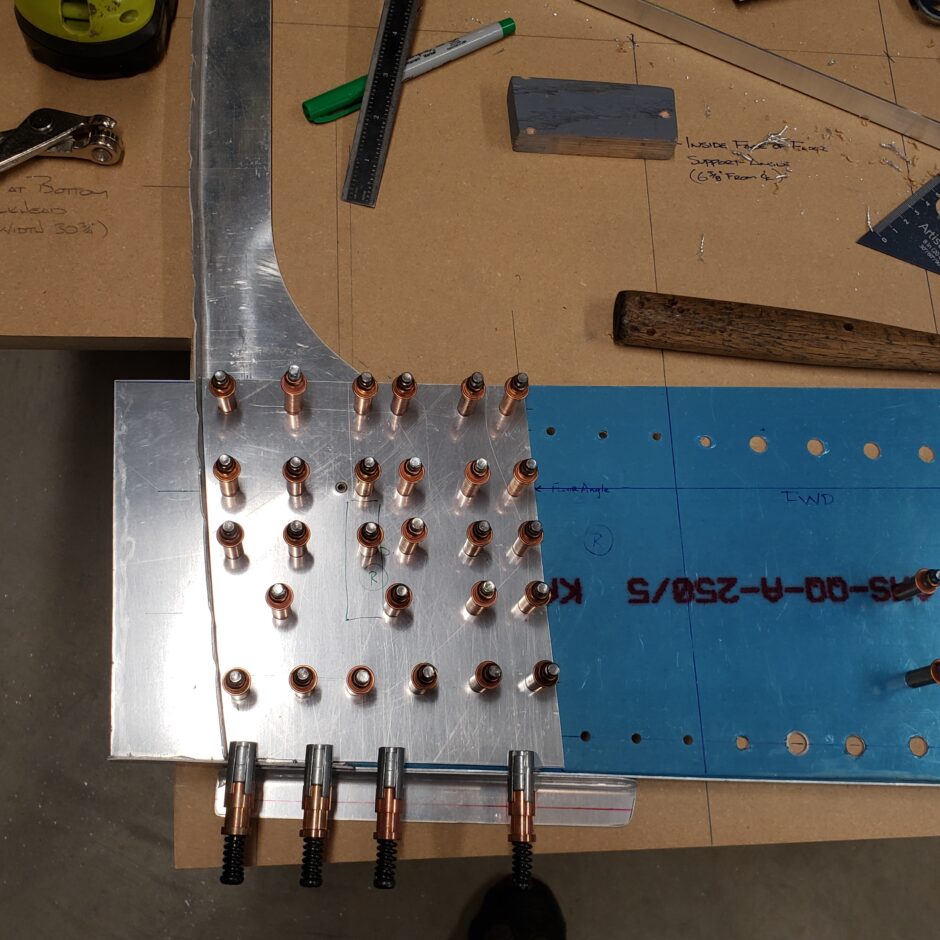
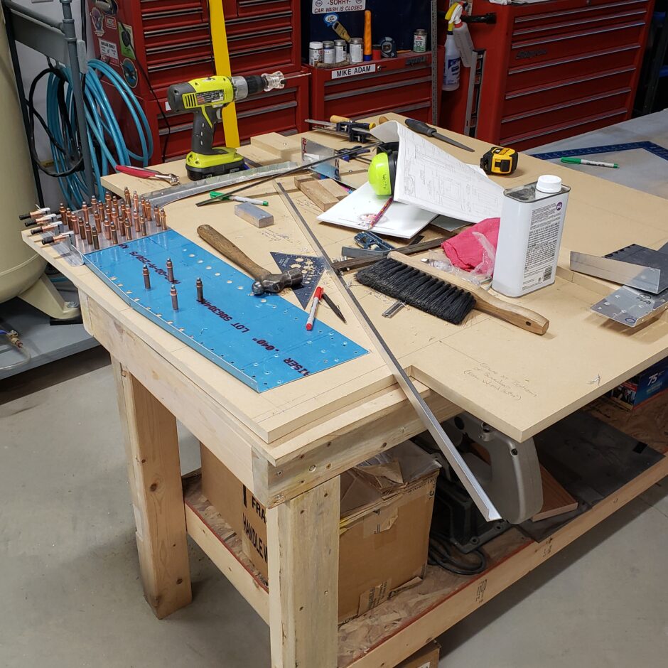
It’s almost time to clean off the workbench…
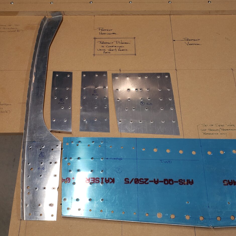
Again, here are the 3 new doubler/splice plates that had to be made. All that work and one half, of one side, of the bulkhead is made. Now to do the same thing…3 more times! The parts have also been dimpled.
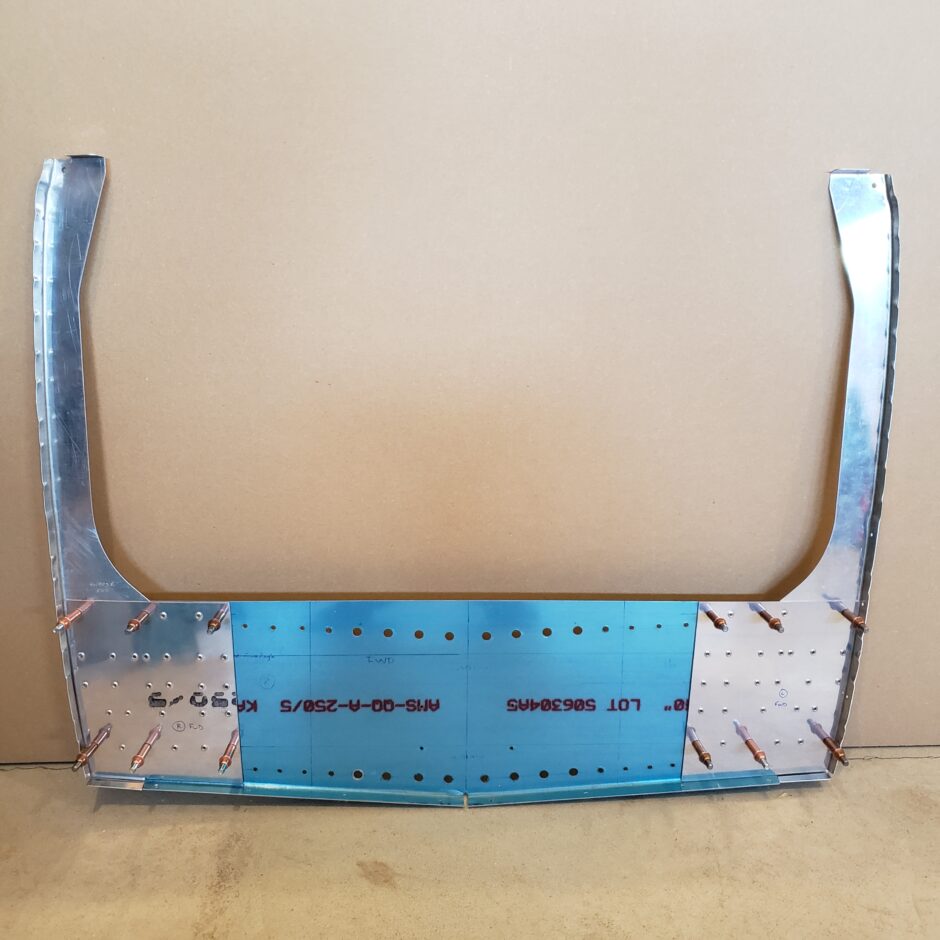
The other side is exactly the same process which is nice. The other side progressed quite a bit quicker.
Please comment. I love to hear from my readers. Thanks again for coming along for this ride, you make my work worthwhile.
Hey!
I had saved your page “August 26, 2020” among my “Favorites” in my web browser. Checked basically every day if you had posted any new post. Hmm, so I missed that you actually created 14 new posts! :O)
Now I have really interesting reading in front of me.
As I said, your blog is extremely interesting and a great source of inspiration.
Thanks!
/ Mats
Sweden
(fuselage jig is made, most basic tools purchased, but no order of parts yet from Team Rocket)
(In the meantime, I’m building a bit on a cafe-racer project https://yamahaxj900.blogspot.com/).
Hi Mats, I’m glad I have been able to sneak a few updates in for you to enjoy! Very cool project you have on the go as well!
Great to see your progress, you are a great inspiration.
Thanks!
Hi Mats, thanks for your support!
Long time no talk. I have finished my wings and am currently building the F404. This page has been super helpful thanks🙂
Hey Bud! I’m so happy to hear that my efforts have been helpful! Keep up the good work.