As I slowly keep working to get the work on the F-404 bulkhead wrapped up, today I worked on the F-404F lower skin panel. This is another part of the F1 bulkhead that needed to fabricated due to extra width of the modified part.
In the picture below, you can see that I used the original part from the RV-4 as a template for the new part. I started by cutting a strip of 0.032 aluminum for the new part. The width of the new part has to be the same as the original F-404F strip. I didn’t worry about the length. I just make sure it was extra long and can trim the excess later.
I also marked the center, as this part has a slight bend in it.
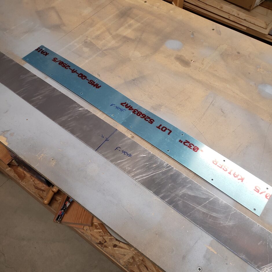
The picture below shows the bend in the skin. You don’t have to be too particular here, just make sure that it mates nicely (flush) to the underside of the F-404 bulkhead assembly.
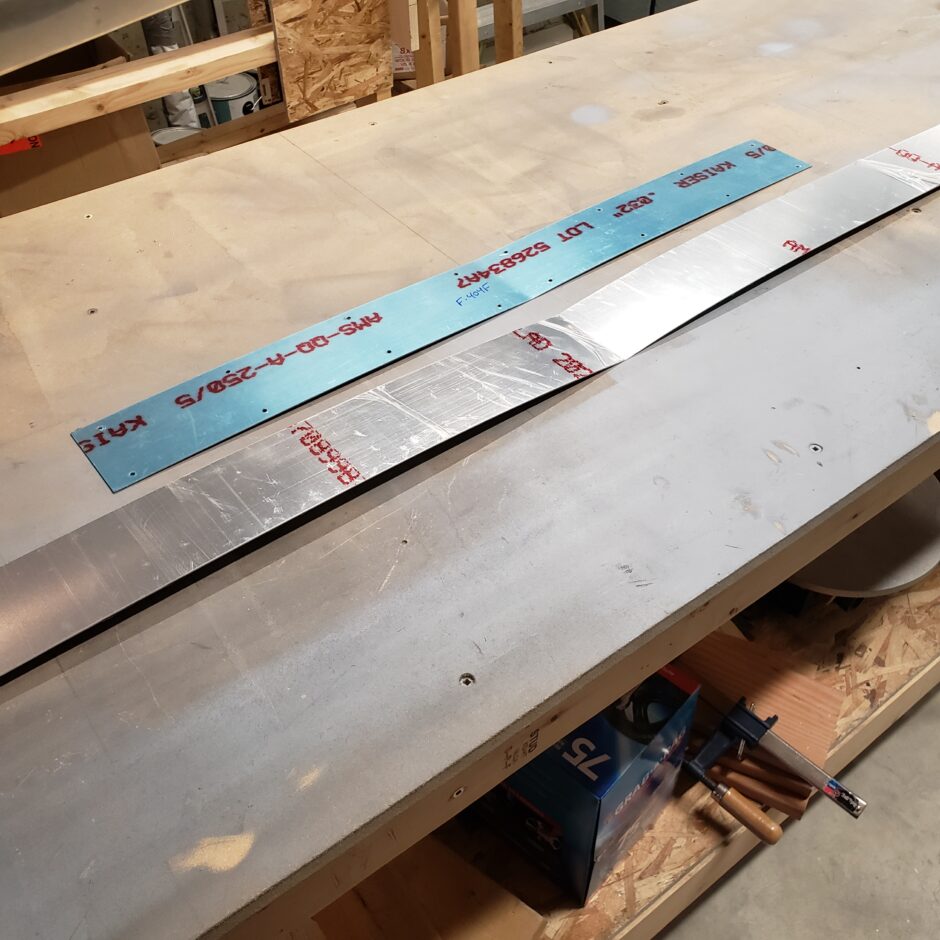
Next I aligned both parts on the middle centerline and clamped them in place. I used the original part as a template to match drill the holes. These holes are pre-drilled by the factory for the bulkhead when in the jig.
In this picture you can also see the generous material I left on either side for trimming.
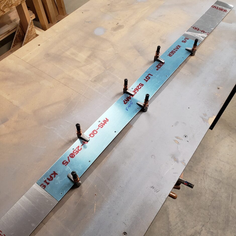
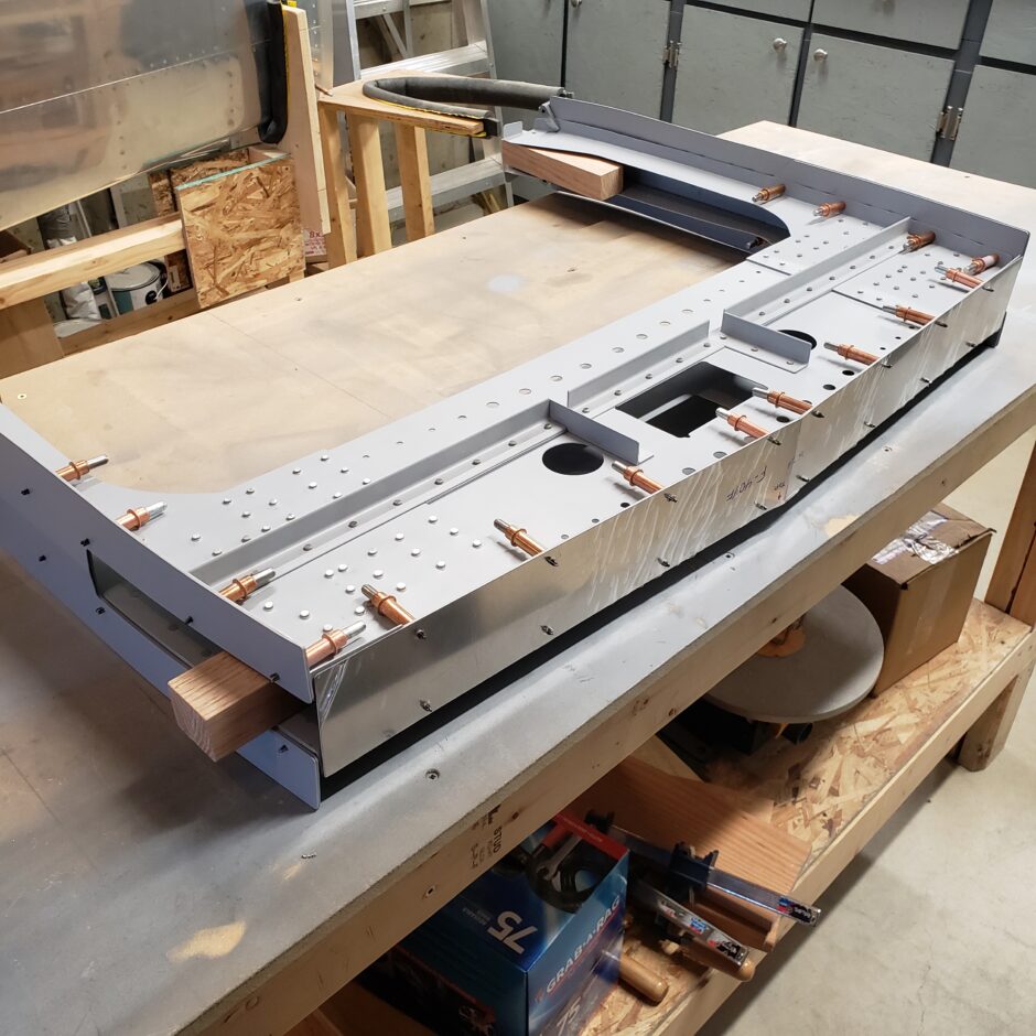
The picture below shows the new F-404F skin in place on the bulkhead and after the ends have been trimmed.
Match Drilling: Spar to Bulkhead
Now that all parts of the bulkhead have been made and the bulkhead is an assembly, it is time to assemble it with the wings, so the wing spar bolt holes can be match drilled to the bulkhead extension pieces. This is a pretty straightforward task. I did this one side of the bulkhead at a time.
I had to clamp the assembly quite a bit as it’s really flimsy! Best not to do this with one person (trust me … wink!)
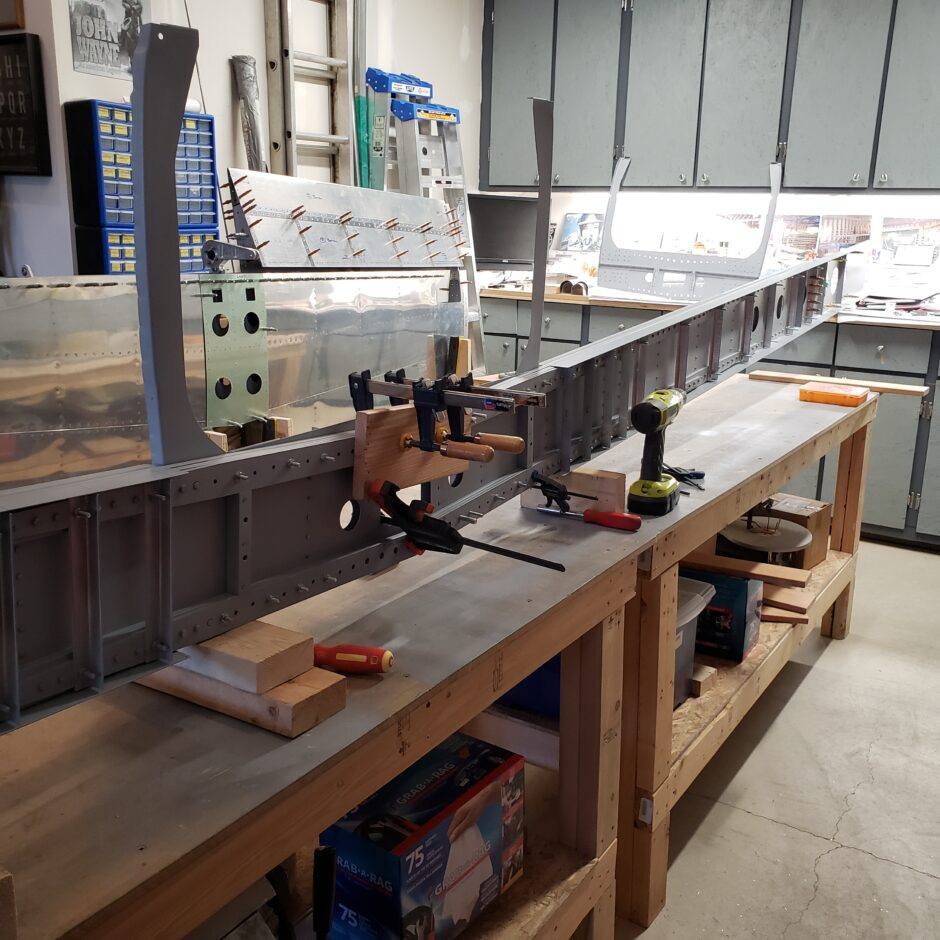
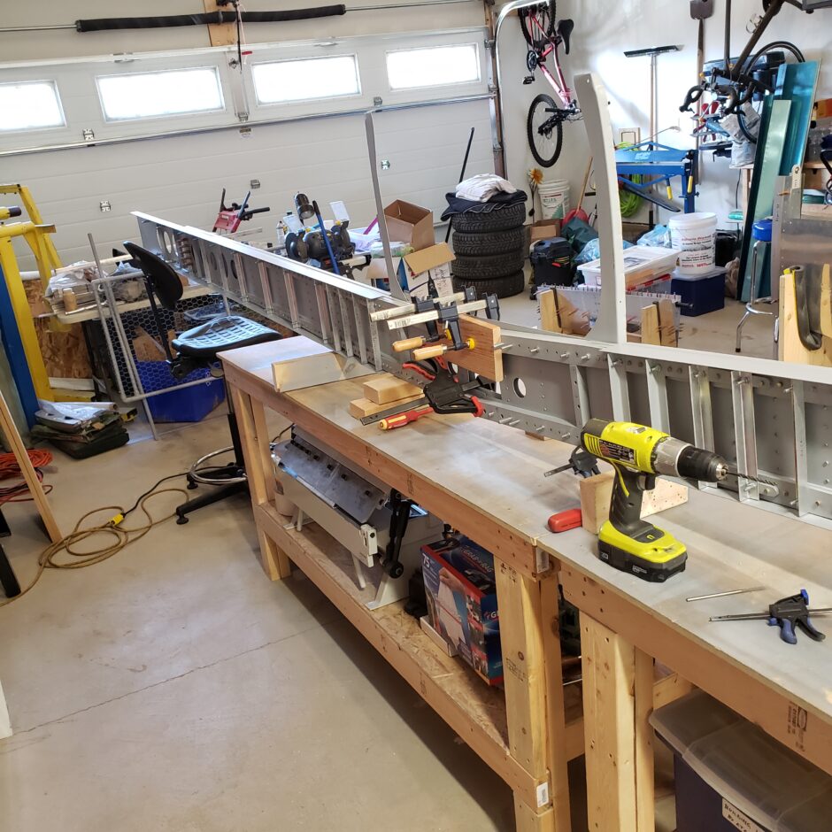
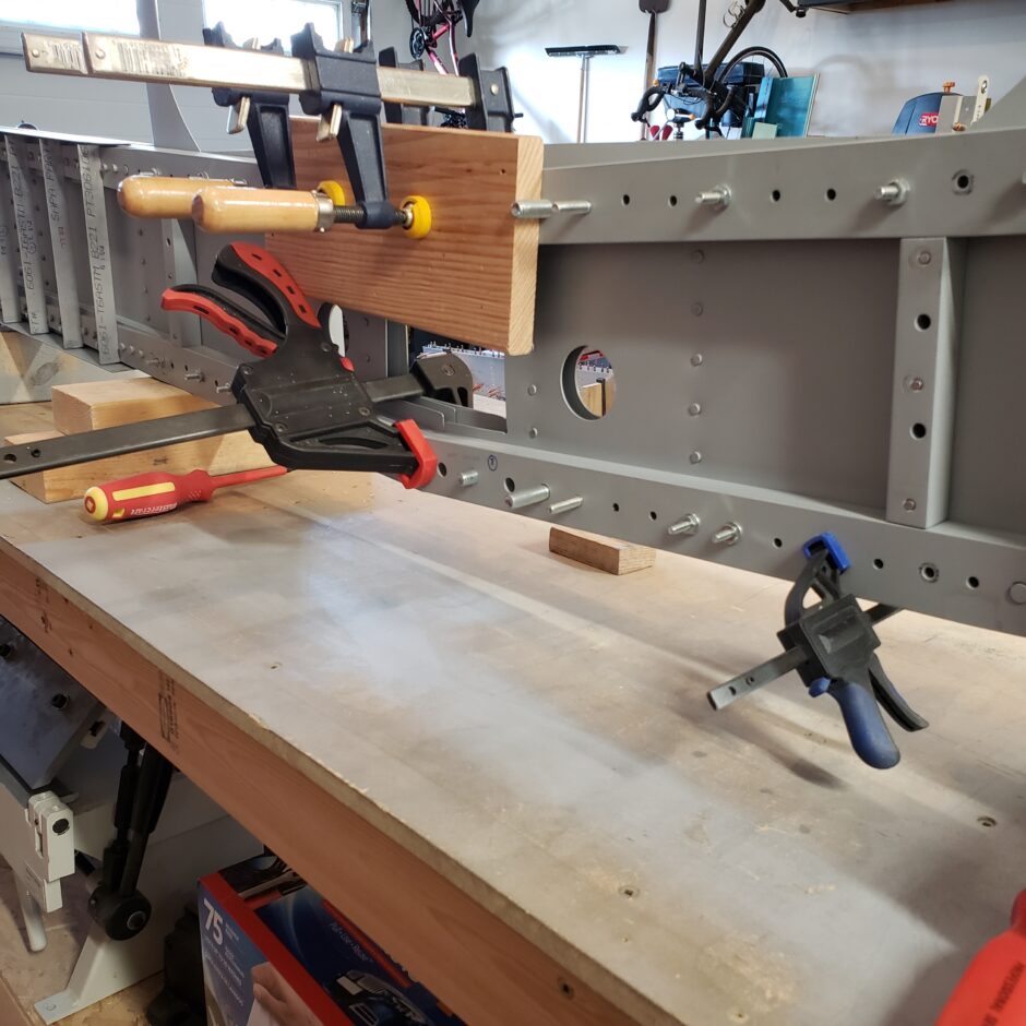
In the picture below, you can see where the new bolt hole are dilled in the doubler plate. Again, this is why you take a lot of time in the planning and layout early on, so that the rivets you install, don’t interfere with these bolt holes. The lower side isn’t too bad, but the upper row of bolts things get pretty tight.
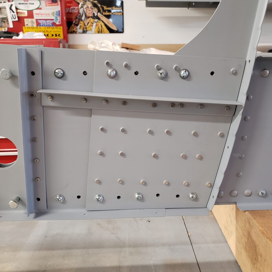
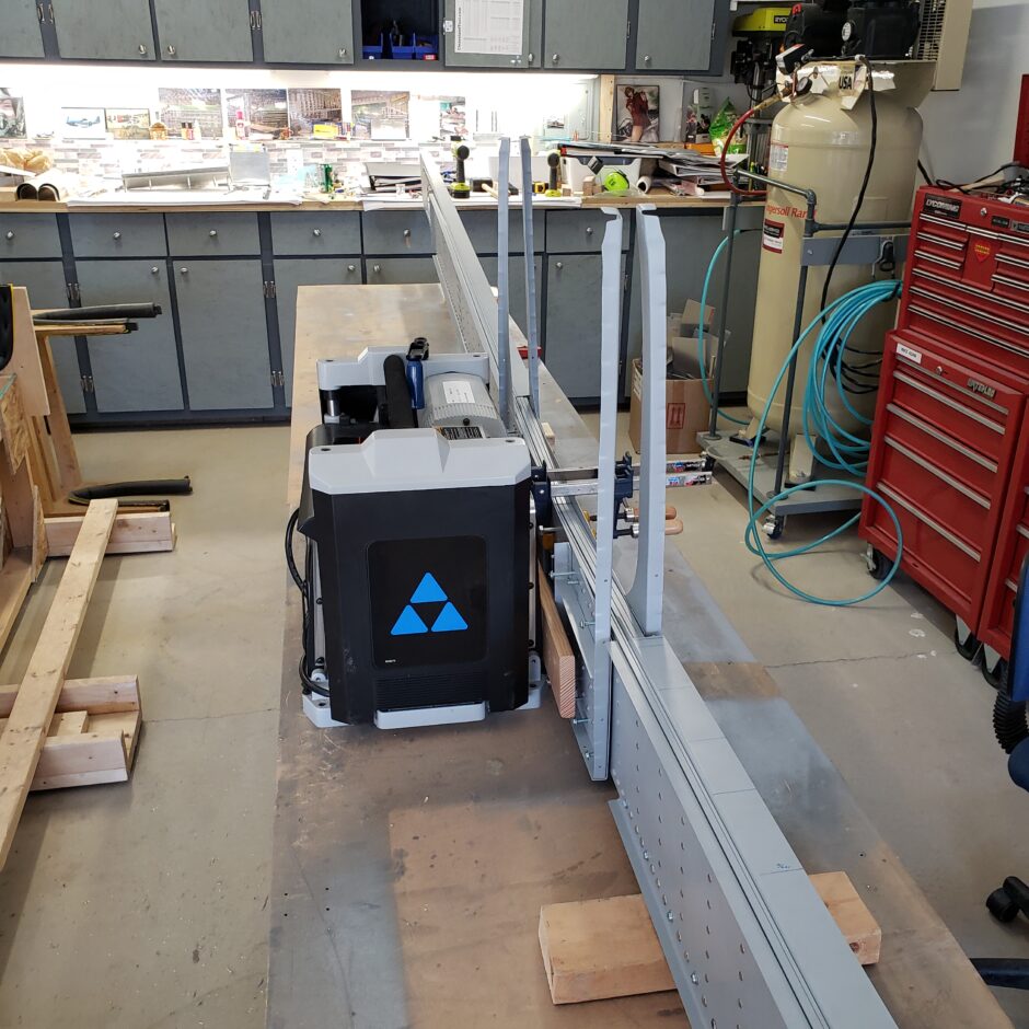
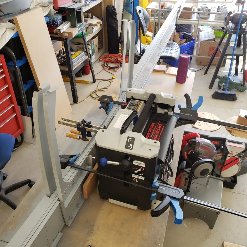
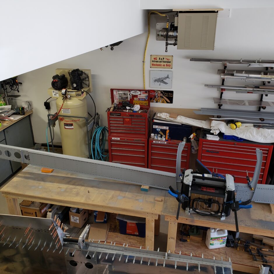
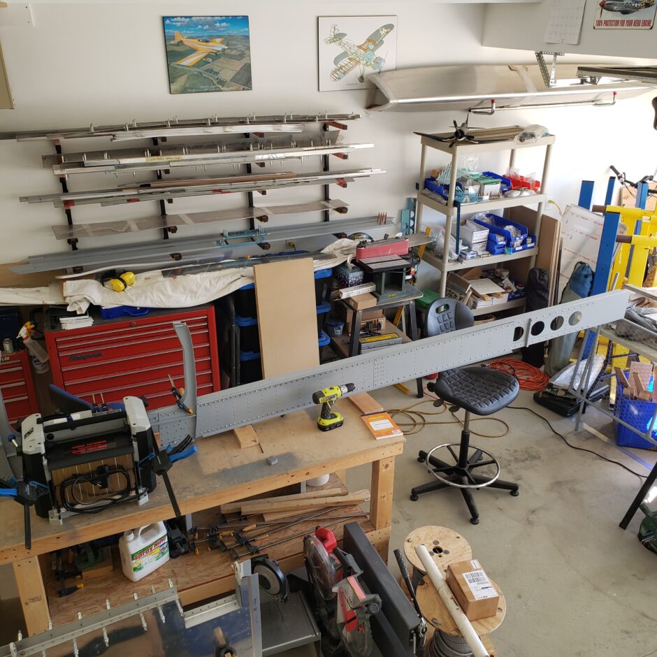
Once one side of the bulkhead is drilled, the other side can be placed, clamped and backdrilled. There is a good bit of weight here that wants to flop all over the place, which is why I found the table top planer was heavy enough to help support the assembly without moving as I drilled.
A few last holes
Wrapping up the work on the F-404 bulkhead I had just a few last holes to drill. These holes are also pre-drilled in the RV-4 factory jig. However, since the extension doublers have covered over the original bulkhead frame in this part, the front and aft sides of the bulkhead need to be match drilled to these holes in the main wing spar.
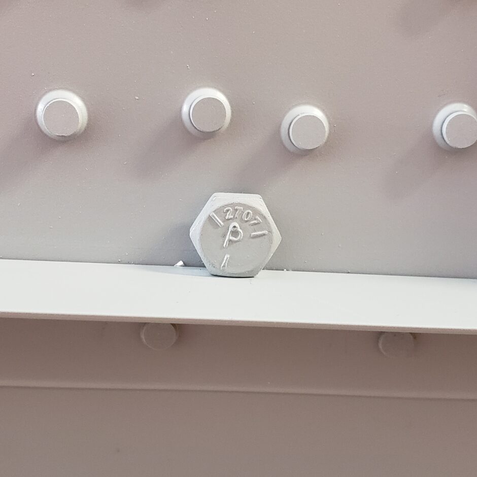
In hindsight, this is another place to be careful of for final spacing. As I located my floor board support angles as per the dimensions in the HRII plans, this all worked out, but as you can see in the next picture, there is just enough room for the bolt head to fit without interference with the floor board angle.
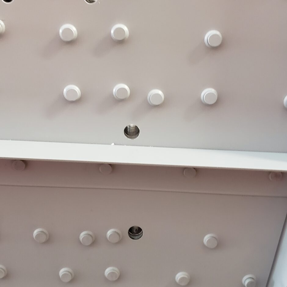
Note the close tolerance between the bolt and the angle.
Please comment. I love to hear from my readers. Thanks again for coming along for this ride, you make my work worthwhile.
Leave a Reply