When starting out on the flaps for the Sport Wing of the F1 Rocket, the first step is to shorten the flap spar that comes in the RV-4 wing kit. In the picture below, you can see that I have the cut lines marked out, and I also have the top and bottom of the flap spar identified. The spar is not symmetrical. There are slight differences in the top and bottom angles of the spar, so make sure that you keep straight which side is up and which is down!!
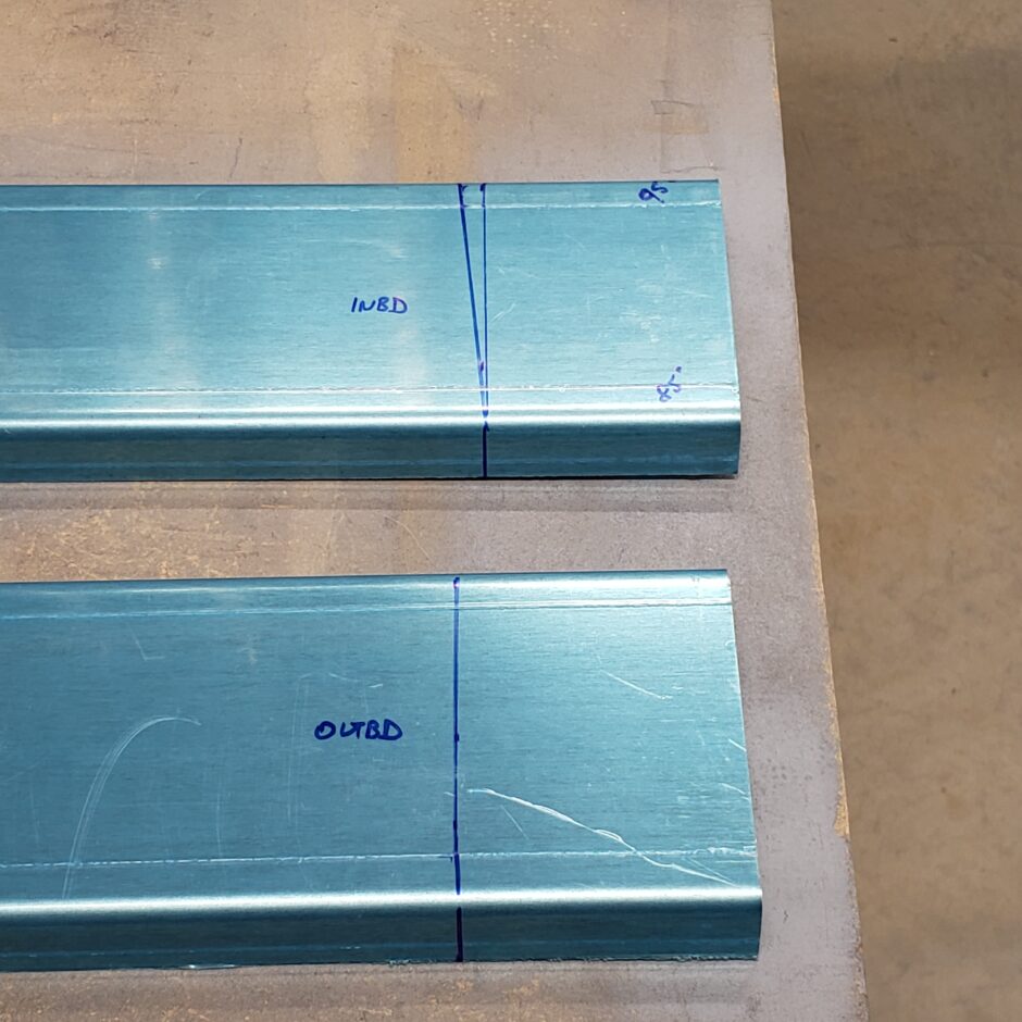
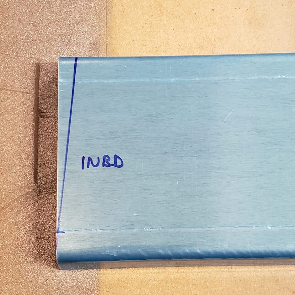
Once I cut the spar to length, I then needed to make a cut to angle the inboard end of the spar.

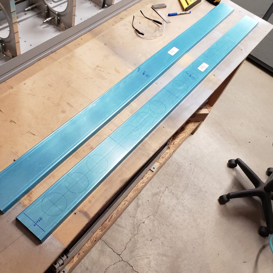
As the flap spar is not predrilled for the lightening holes, I needed to do the layout for these. These are not shown in the Harmon Rocket II drawings. The hole size details are specified in Drawing # 15 from the RV-4 plans, which are 2 1/4 inch diameter. You’ll need 13 holes and I started measuring 3 inches in from the tip. The layout worked beautifully!
As the flap skins are pre-punched, the next thing I did was marking centerlines on the FL-404 and FL-405 ribs, as well as on the spar (FL-403). As shown in the picture below, I clamped the spar to lower surface of the flap skin, making sure that the centerline was visible in all the pre-punched holes. The same goes for aligning the outboard rib, as it too aligns with the pre-punched holes.
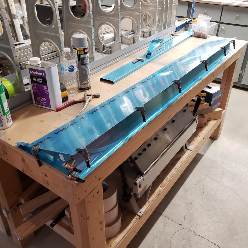
Below is a picture of the other side of the flap with the spar and outboard rib clamped in place.
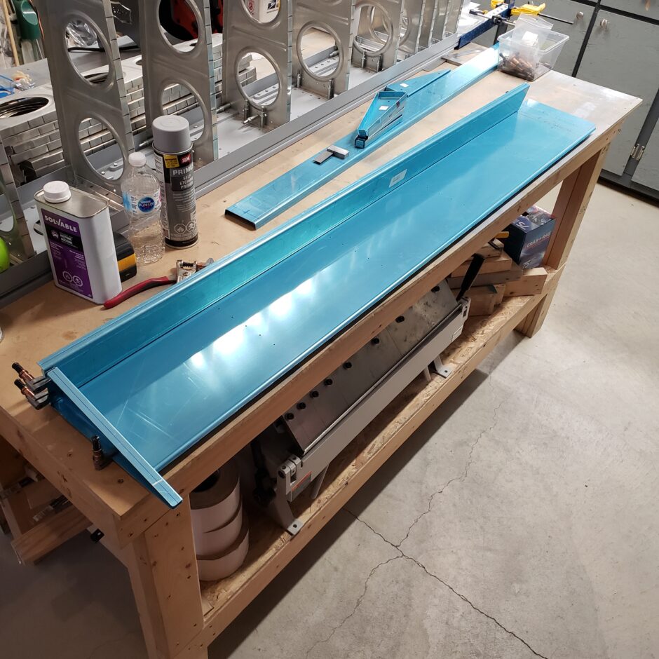
Next up, I started to get the flap ribs mated to the spar. The lower skin is pre-punched, but the ribs are not, so you’ll need to make sure that you have all flanges marked with a centerline, so eventually you can get the ribs properly aligned.
The important part in this process is to make sure that the ribs butt tightly up against the aft side of the spar. You don’t want any gap here, nor is it acceptable to expect to pull any gap together during the riveting process.
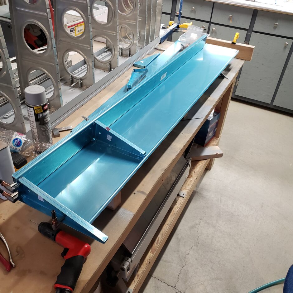
In the picture below, you can see on the left side (between the drawn lightening holes) there is a vertical line drawn on the spar. This is the locating line for the proper placement of the rib.

As the rib is not pre-punched, and here I needed to mark out the centerline of the forward flange and then set the edge distance for the 2 rivet holes. Once this was all laid out, then I drilled a pilot hole for these 2 holes, which will allow me to get the rib set on the spar and then to match drill it to the spar.
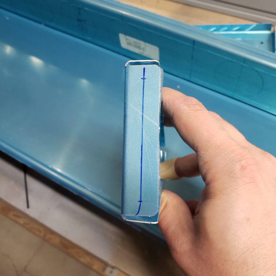
Then I clamped the rib in place starting with the vertical line previous drawn on the spar, and aligning the lower rib flange centerline with the predrilled holes of the lower skin. When I was happy with the location of the rib, I clamped it in place.
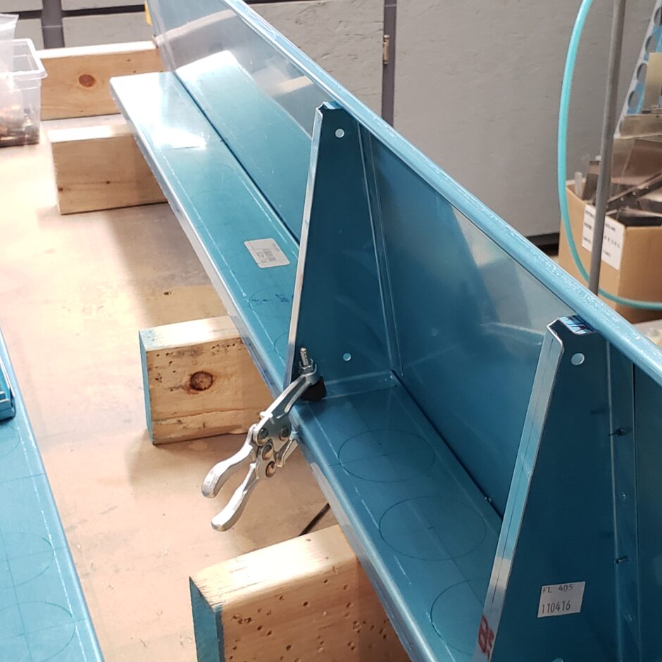
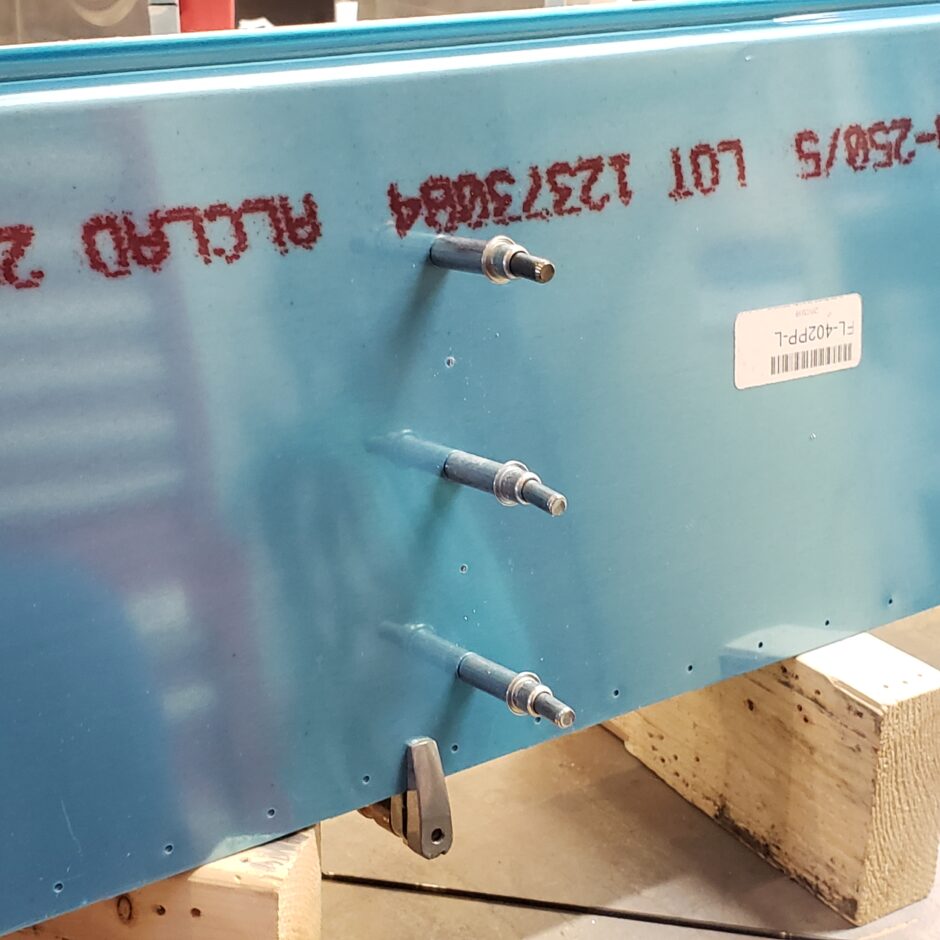
Then I match drilled the lower skin to the rib, picking up all drilled holes on the centerline.
With the rib now cleco’d to the lower skin, I used a small square to ensure that the rib was perfectly vertical. Then I clamped it in place and drilled. When I drilled I used a long 12 inch #40 bit to be able to get inside the flanges to back-drill the spar.

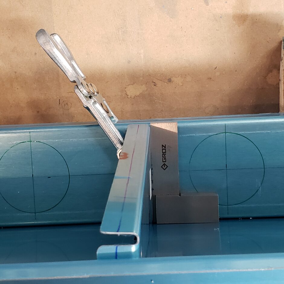
And just link that…the spar is now match drilled to the rib!
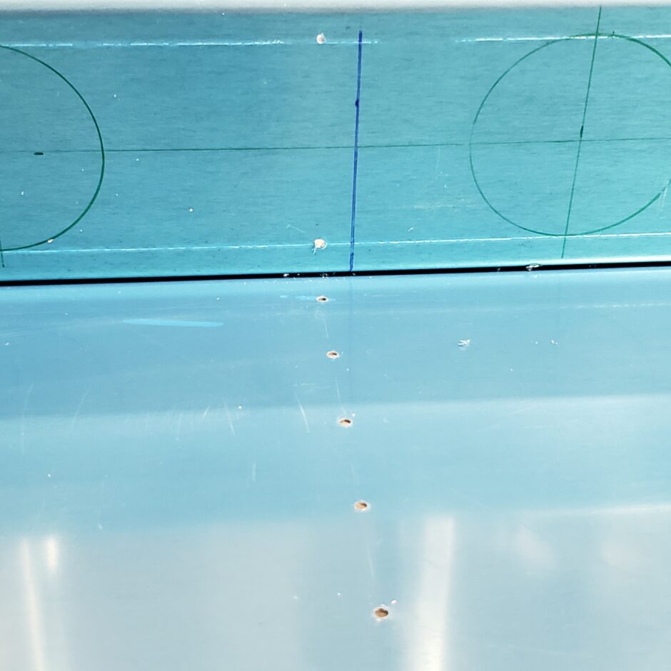
And so the process continues for the rest of the ribs.
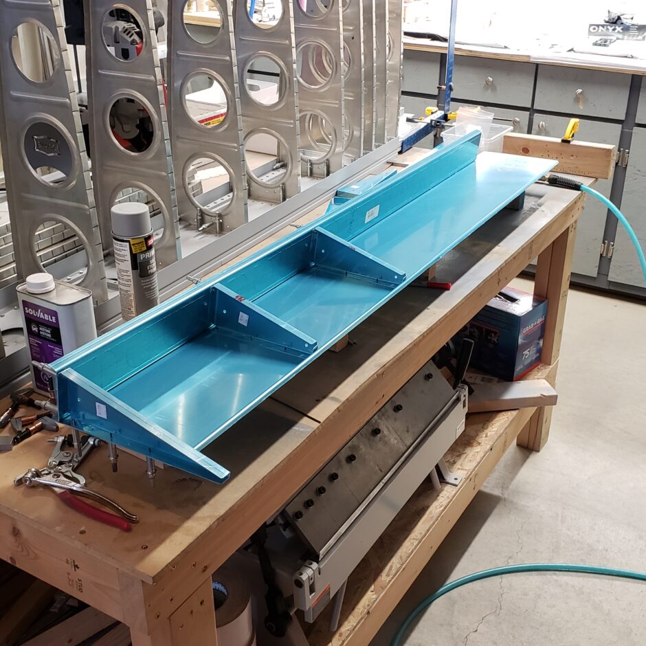

Now having worked my way to the inboard rib, this one takes a bit more planning because of the shortened width of the flap, this inboard rib won’t align with any pre-punched holes. As shown on the picture below, I’ve marked a bunch of layout lines on the lower skin, as well as tracing the final location of the FL-404 inboard rib.
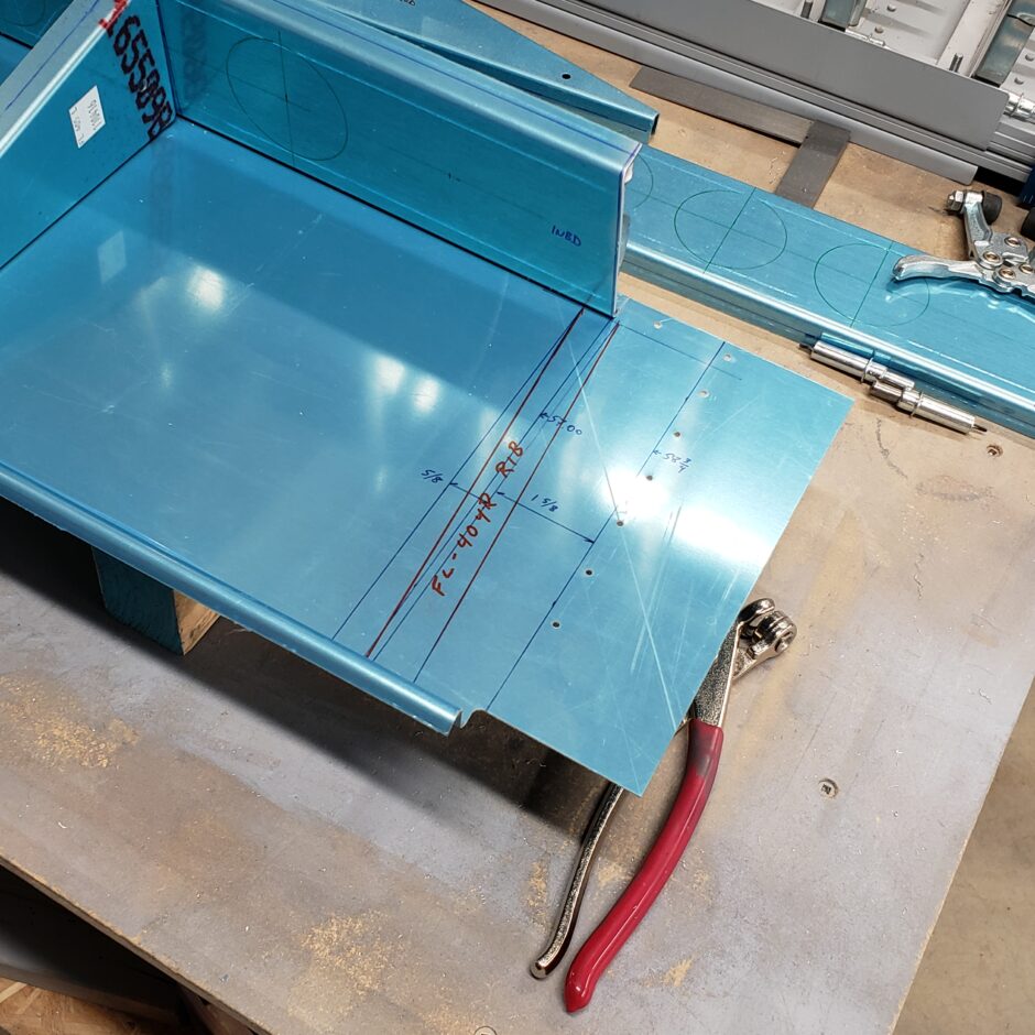
As I didn’t have much time left today to keep working on finishing up the inboard rib, I chose to move on to the getting started on the flap actuator bracket layout.
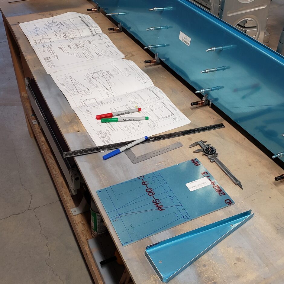
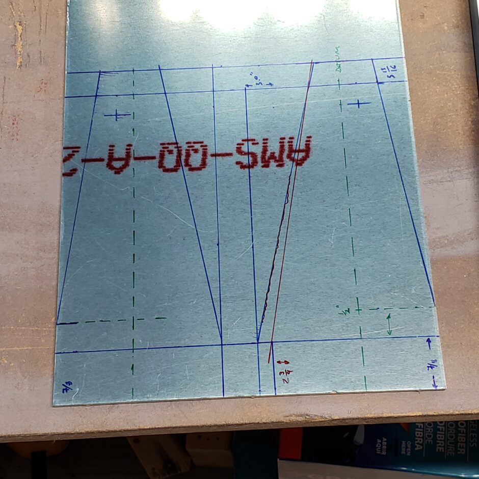
Well, that’s all I can do for today. Please comment. I love to hear from my readers. Thanks again for coming along for this ride, you make my work worthwhile.
Leave a Reply