Good day! Today I’m going to get the fuel tanks back on to the wing assembly and I’m going to work on match drilling the screw hole locations for where the rear tank baffle will attach to the forward side of the wing spar.
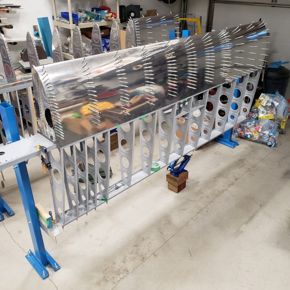
Next I strapped the fuel tank down again to get it perfectly located along the skin butt-joint line drawn along the main spar (top and bottom). Also, I added the red strap this time to make sure I had the leading edge skin and fuel tank skin tight at their seam as well. Once the skin is properly located on the wing, I then marked the location of the tank baffle and where it sits on the forward spar doubler that it will be attached to (See next photo).

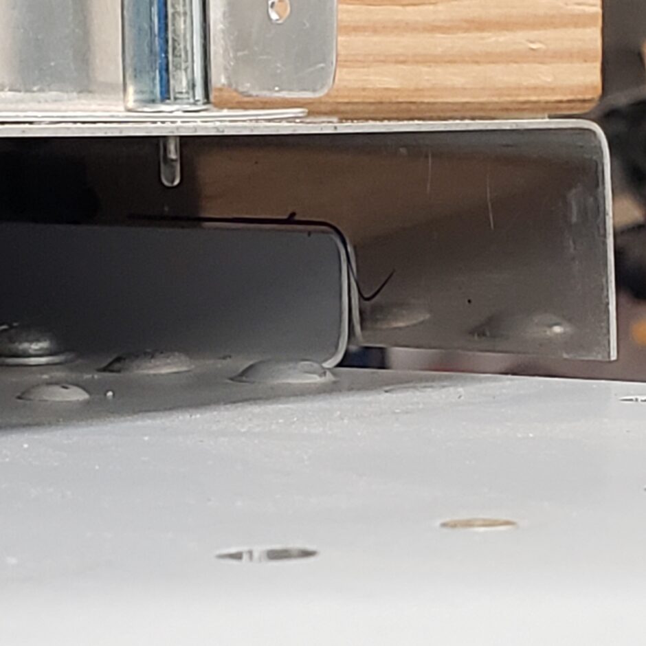
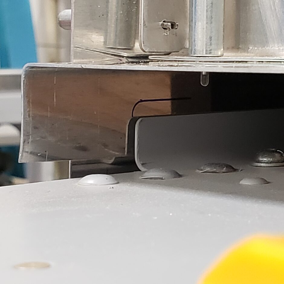
I actually didn’t get a picture while doing this, you’ll see this photo is from the next few steps ahead. I just stuck it in here for you to understand what I’m talking about because this reference mark a VERY IMPORTANT step! You’ll see why in a moment. All I did was trace the spar doubler location onto the tank baffle.
The main reason for all of this is because to drill the tank baffle to the spar, we need to have the skin off to be able to see what we are drilling, and then eventually, we’ll be back drilling the skin, through the screw holes in the spar doubler and tank baffle. But since the skin will be off on one side of the tank, we’ll need some way to locate the tank baffle in the proper location until we have enough holes drilled to get it securely cleco’d in place.
Another point you may want to consider doing right now, is to also remove the fixed leading edge so that you can get access to the outboard end of the tank and also make the same reference marks out on that end of the tank baffle as well.
So the next step is to open up one side of the tank skin.
Building Tip! If you don’t already have a pneumatic cleco gun for installing and removing clecos, now is a good time to get one. Especially if you are building an F1 with these extended range tanks!

With the tank skin off the one side, we have nothing to hold the tank baffle down in the correct position, and it needs to be properly located before we can start drilling.
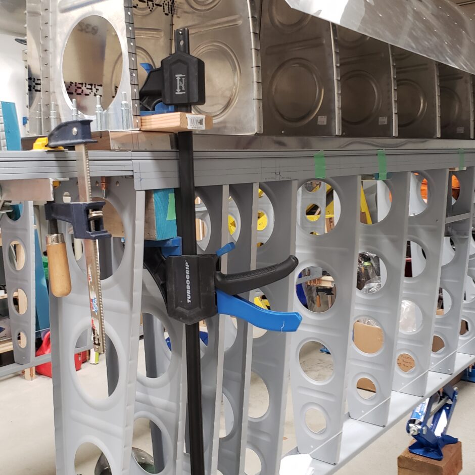
The way I got the baffle to get back into alignment was to use a large clamp and a scrap piece of wood to be able to apply even pressure along the width of the tank baffle, so both the upper and lower side could be pressed into position.
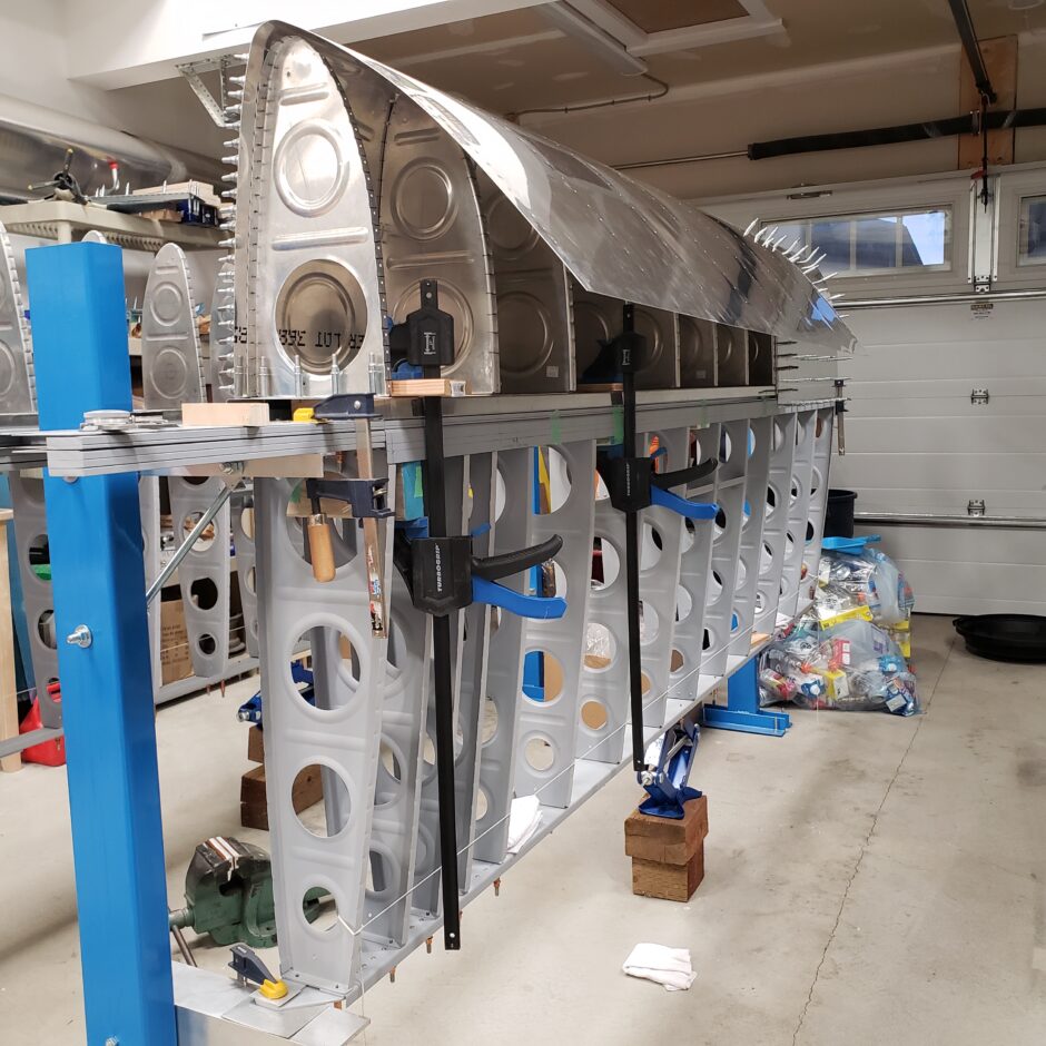
When the alignment was all set, and measurements were double checked. Then I drilled my first hole at the inboard end. This line of fastener holes we are drilling are for the screws that will be in these locations to attach the tank to the wing spar. Nut plates will eventually be installed on the inside of this channel.
But for now, this first hole will be used as an anchor location and I’m going to install a pulled rivet to hold the baffle in place, so I can drill the other holes. For these temporary anchor points, I’ll have 4 of these per side. One on each end, and to somewhere evenly in the middle of the span. This will hold the baffle in place to allow me to work. Then when all the other holes are drilled, I’ll come back and drill out the rivets.
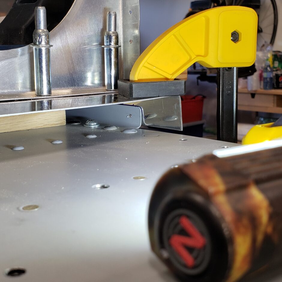

For the rivets I used some LP4-3 rivets as I have lots of them.
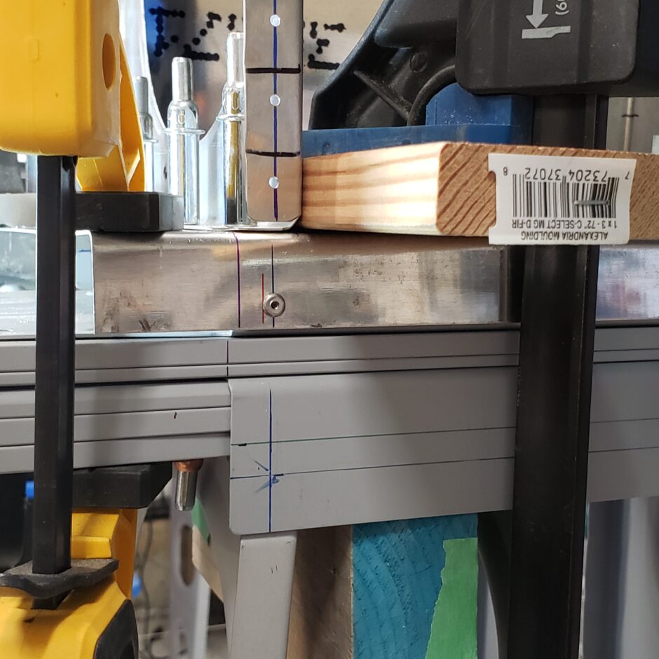
The key in locating these holes is to make sure you are centered on this little flange. There isn’t much room for error here, but it’s not too bad to work with.
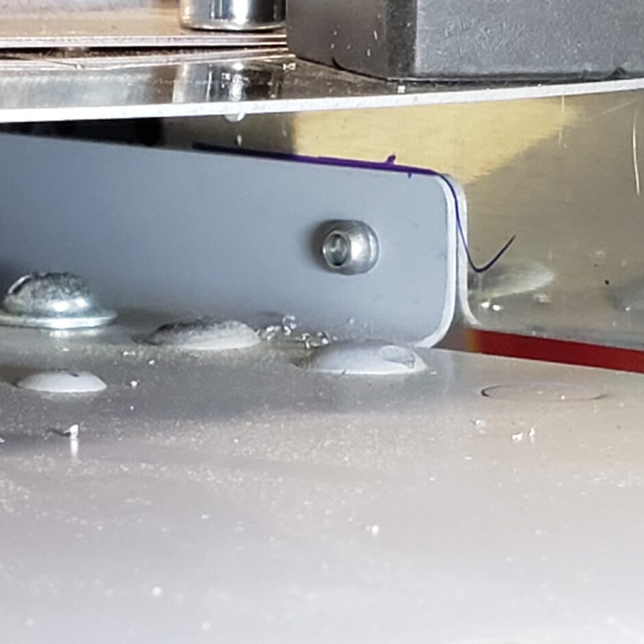
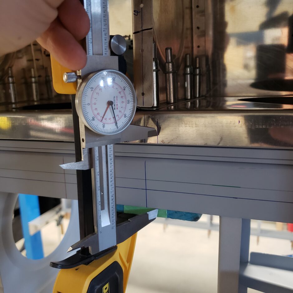
These are some of the ways that I checked my measurements along the way to make sure the tank baffle was properly located. In the picture below, I used the first hole in the rib, as these were all drilled to the same dimension, measuring up from the edge of the spar.
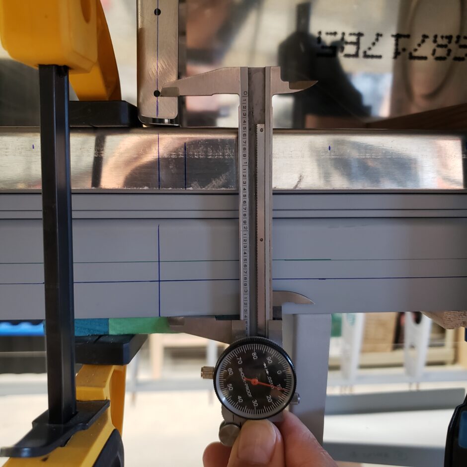
Then I was able to check and set my measurement for the hole location along the tank baffle.
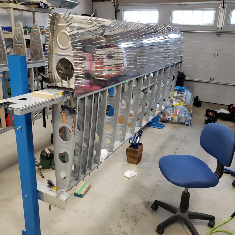
So then with all the holes drilled, and the anchor pulled rivets in place, I had the skin all back on. What you can expect to find while doing this, is that you’ll have the skin up on one side to work, then you’ll put it back down. Then you’ll open up the other side…then you’ll cleco it back down…then open up the first side again…etc. It’s very much a back and forth process that is quite monotonous.
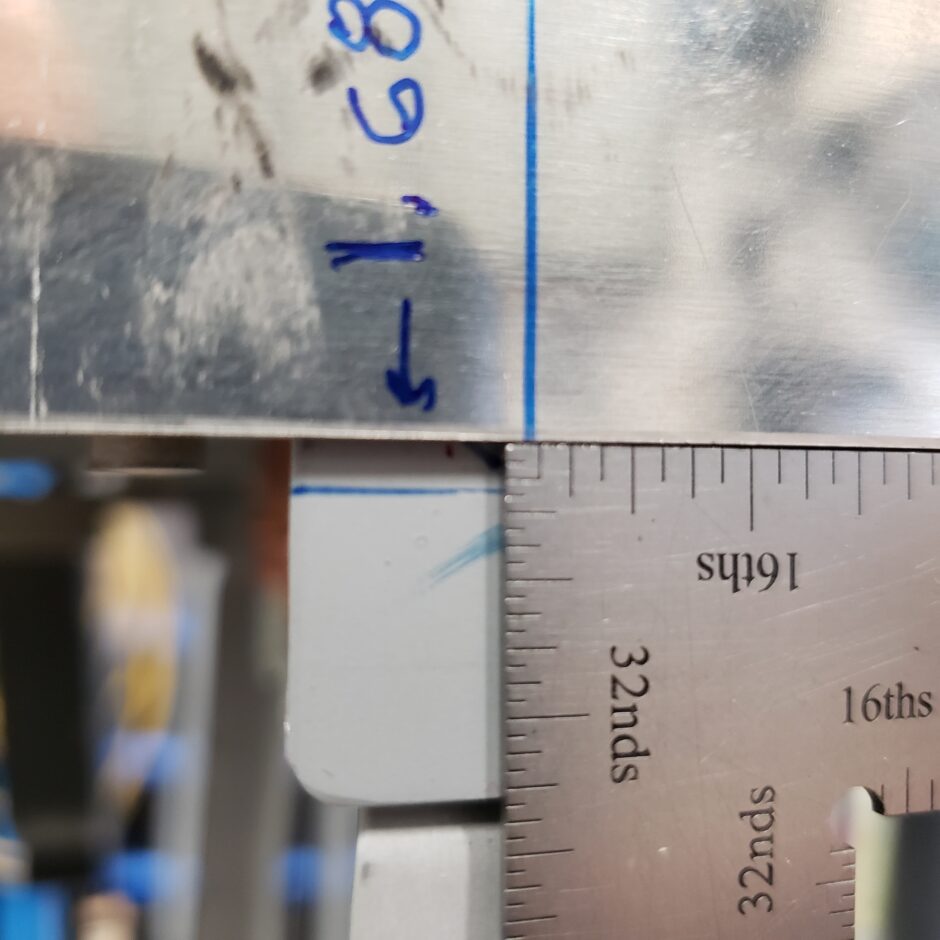
So now I’m ready to back drill through these holes, so I can finally match drill this fastener row to the skin. The only issue is, as you can see below, I’m 3/32-inch off my skin joint butt-line at the inboard end, on the top side of the skin. In a way, this goes to show you how much pressure the straps place on the tank skin to get it in place. But now that I have to have one side of the tank open to be able to back-drill the skin, I don’t have that clamping pressure.
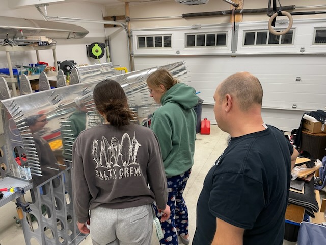
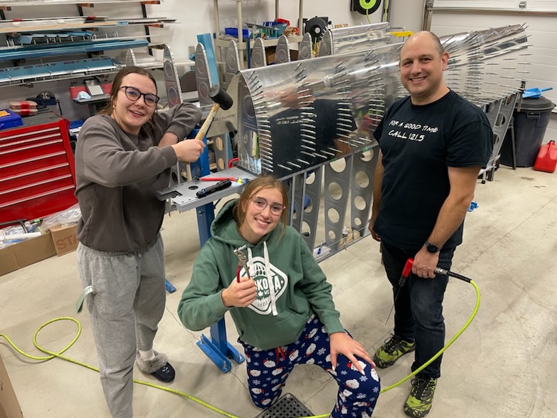
So I called in some reinforcements to give me a bit of extra pressure to get the skin in place. This way I could at least drill the first couple of holes and get some clecos in place to hole the assembly. With the help of my hockey billet girls, I was able to get this done. I was also able to take this opportunity to introduce them to the world of homebuilt aircraft. They’ve seen me working away in the past, but they haven’t had an opportunity to actually be able to actively take part. So tonight I was grateful for their help.

I had the girls start by helping me with clecos as I drilled the holes.
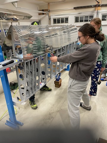
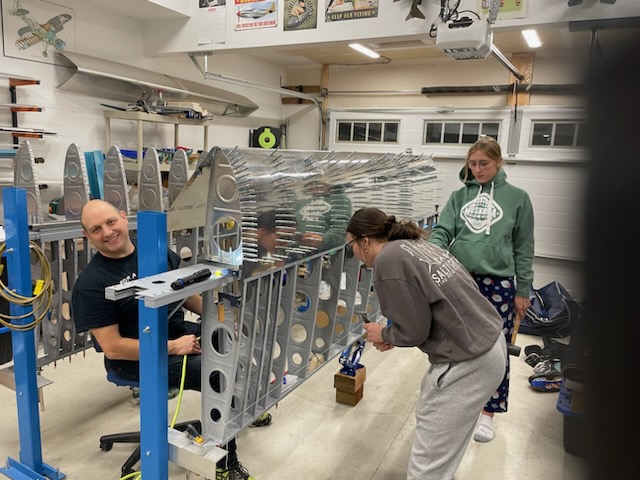
Then we ventured into drilling. The one girl was happy to try her hand at the new skill, however the other was too hesitant as she didn’t want to screw anything up. This was pretty easy drilling though, as you’re drilling through the tank baffle and spar channel (using it as a drill guide) across to the holes opposite (again using as a drill guide), to be able to back drill the skin, inside to out.
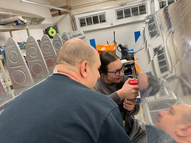
This second picture better represents how you need to have the skin on one side opened up, so you can cross drill the skin. Here we are using a 12-inch #40 drill bit to make the pilot hole. Eventually, these holes will be drilled out to #19 for #8 size screws.
Builder Tip: Read the plans for the fuel tank assembly, as there are some notes about not drilling these holes to the final size until after the tank has been sealed!
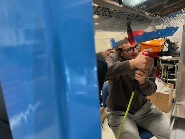
Tonight’s building session was a lot of fun. It was great to be able to have the girls out helping me, and to have my lovely wife working the camera to capture these cherished moments.
With one side of the tank all drilled, in my next build session I’ll be able to again, close up the open side, open up the other side and carry on drilling more holes.
That’s all for today folks. Please comment. I love to hear from my readers. Thanks again for coming along for this ride, you make my work worthwhile.
Leave a Reply