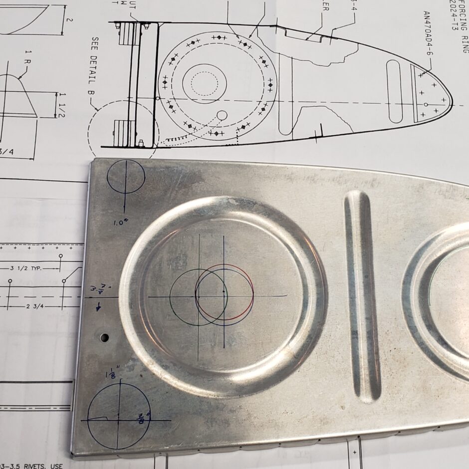
Today I’m working on the fuel tank rib layout for all the various holes that need to be added to the ribs. These are fuel transfer holes, venting hole, and holes for the fuel vent line.
There are significant differences here between the RV-4 plans and the HRII Sport Wing plans. In particular, the fuel vent holes on the upper side of each rib are enlarged to a 1-inch diameter size hole, vs the 1/4-inch size vent hole on the RV-4 drawings. The other 2 larger vent holes remain the same at the 1 1/2-inch size. Additionally, the fuel vent line hole goes just aft of the forward 1-inch fuel vent hole.

Another difference between the various plans are for the vent hole located in the center of the aft round rib stiffener stamping. The HRII plans call for the hole to be located 3 7/8-inch up from the bottom of the rib, and 3-inches forward of the aft flange (see the green circle in the image below). The RV-4 rib layout calls for this hole to be located in the center of that stamping. The location dimensions for this location are 4-inches up and 3 5/8-inch forward (red circle). I then split the difference and added the blue circle (just disregard that one, I didn’t use it).
After looking at pictures of several other F1 Rockets, I decided to stick with the hole location as shown in the RV-4 plans to keep this vent hole centered on the stamped area, which is what many other builders have done. As this is a venting hole and just allows fuel to transfer from one tank bay to the other, I don’t see significant difference between the two locations. If anyone knows of any reason for the change between the RV-4 and HRII drawings, please comment below to let me know.

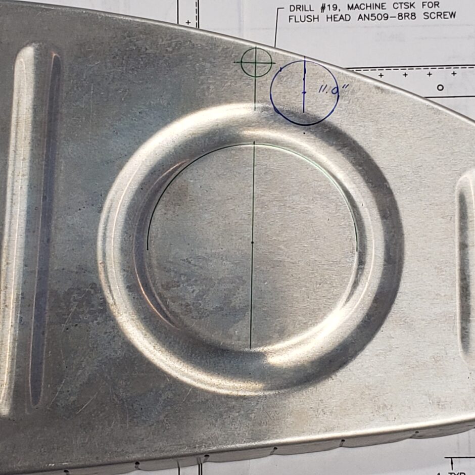
Here are the close up details for the 1-inch vent hole at the forward end of the rib, along with the fuel line vent hole which is 7/16-inch diameter to accept the SB437-4 plastic bushing. You can also see that the vent hole is located at 11-inches forward of the aft flange. The HRII plans leave much to be desired in detailing the location of the fuel vent line hole location, as it’s not even specified on the drawings. The additional instructions provided on Vince’s Rocket website, just state that this hole needs to be located just aft of the 1-inch vent hole. As you can see below, it works out pretty well if you locate that vent line hole with the center of the stamped hole.

Well, that’s all I have for today. Please comment. I love to hear from my readers. Thanks again for coming along for this ride, you make my work worthwhile.
Leave a Reply