Good day, today I’m working on the fuel tank trap door which is located on the 2nd inboard rib from the root. The purpose of the trap door is to create a bit of a header tank in the inboard fuel tank bay, acting as a check valve allowing fuel to flow into that bay but is slow to flow back out.
I’m starting on the left tank, and having not planned ahead properly, I drilled one of the main fuel transfer holes in the middle of the second rib, and now I have to patch it. This is one of those gotcha areas because both the RV-4 and the HRII Sport Wing plans are pretty light on the details for this particular job. I mostly figured it out by reviewing a bunch of other Van’s aircraft builder logs and chatting with my community. All in all it worked out, but definitely do your homework before you begin the trap door. It’s not hard, but it will surely speed up your work if you’re prepared for it.
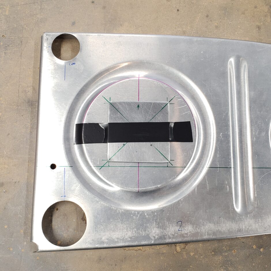
In the picture below, I made a 0.025 plate to be riveted on to the rib, thus blocking this hole. The trap door will be installed on the lower hole. On this rib, and only this rib, it’s best to not drill this hole. It’s not a lot of work saved, but any work saved is a bonus.

I couldn’t figure out how to hold the plate in position while I got the initial holes drilled. I found that a piece of electrical tape worked well until I could get a few clecos in place.
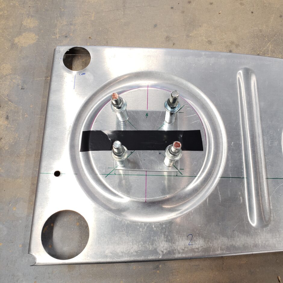
All ready for riveting.
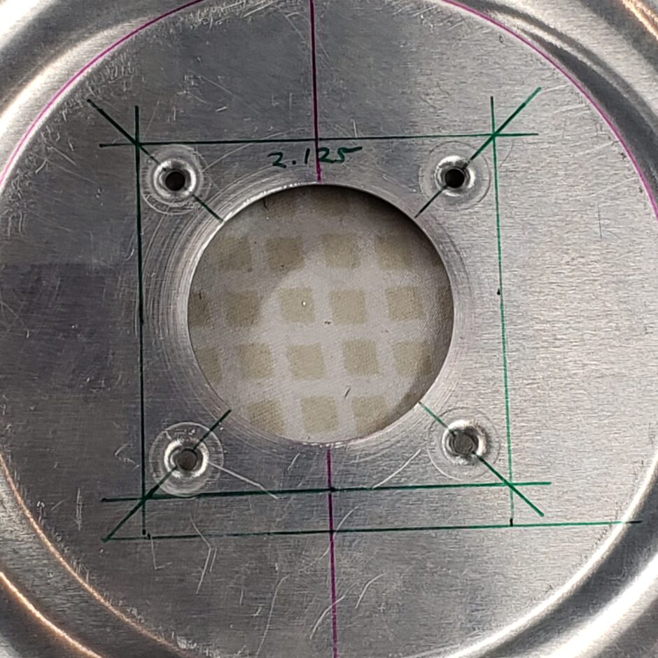
Trap Doors
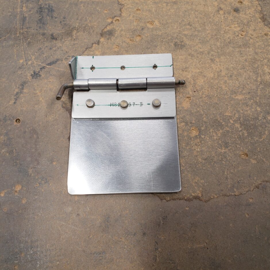
The trap doors are a simple hinge and door assembly. As you can see it’s pretty self explanatory what happens here. Note that on the one side of the hinge, a segment of the hinge is bent up to act as a travel stop for the door.

And here it is with the door riveted on. The thing to keep in mind here is to keep the flat side flat, as it needs to be flat against the rib. So be sure to use countersunk rivets here. I dimpled the door and countersunk the holes in the hinge.
Again, no real guidance from the plans here on how to get it oriented. I just aimed to have the door horizontal and perpendicular with the aft rib flange, and to have it cover the fuel transfer hole.
Again, another example of the plans not really giving much guidance to follow, I totally guessed at the length of the hinge. It turns out that its too long and extends over the formed stiffener ring on the rib with nothing to rivet the third hole to.
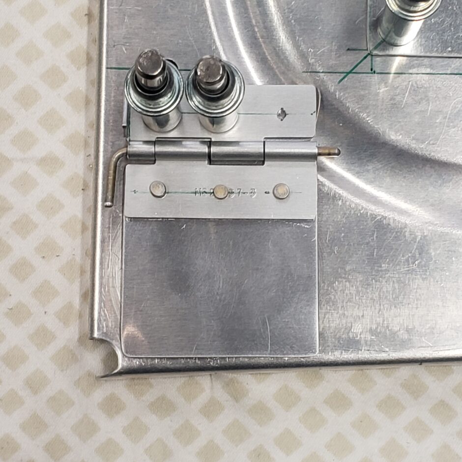
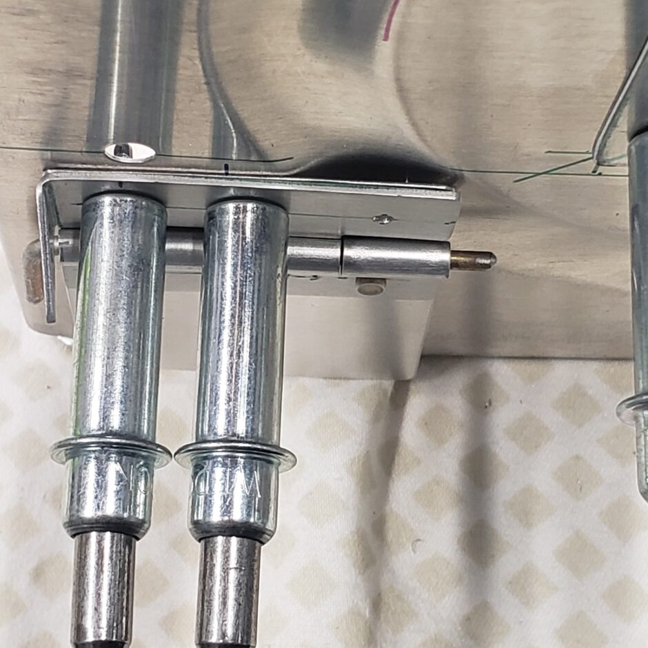
My solution to the hinge was to just cut the excess off and trim it to match the stiffener ring. Two rivets is still sufficient to hold the trap door assembly on as there is no load on this part. Also take note of the position of the hinge pin. The pin is installed in the position purposely, because when the rear tank baffle is on, the pin won’t be able to migrate out, thus securing the hinge pin in place.
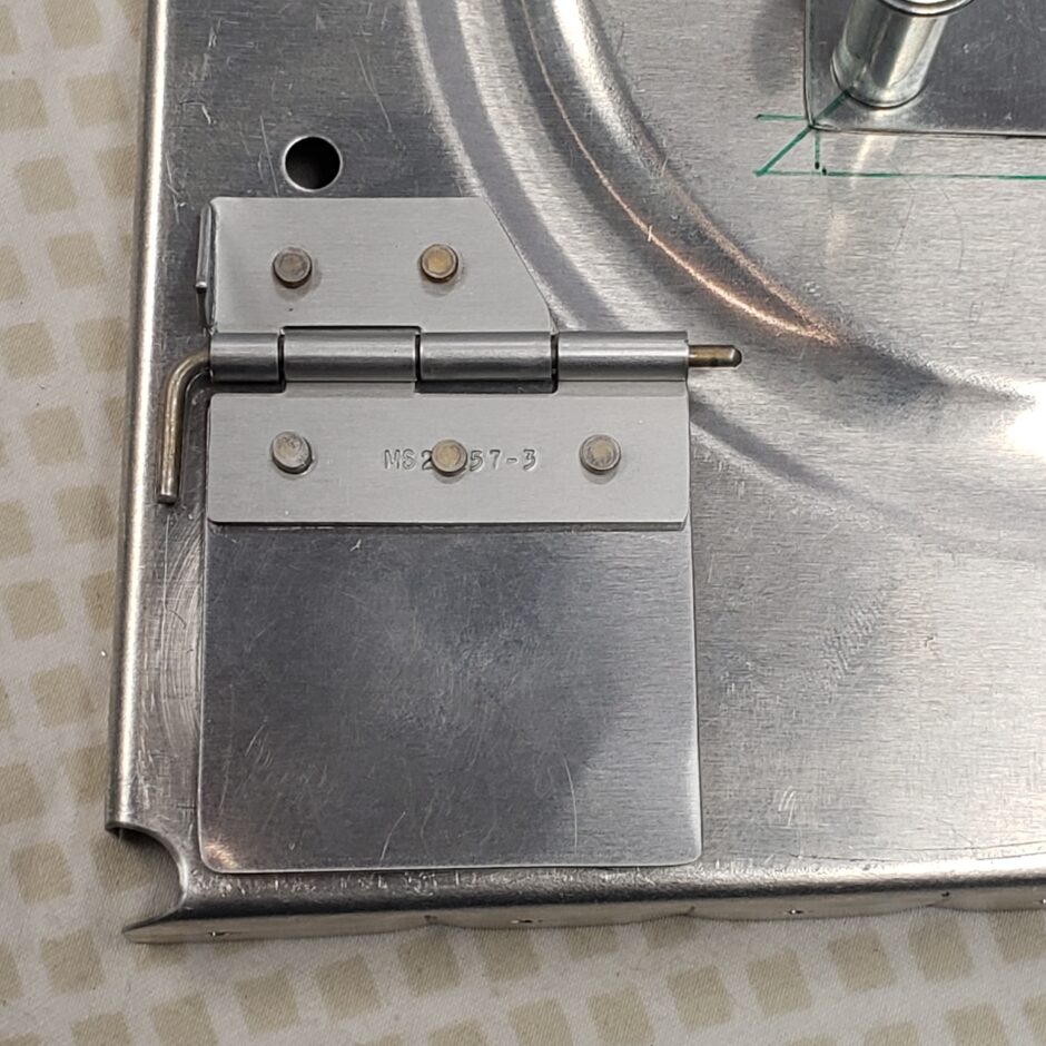
And here’s the finished product!
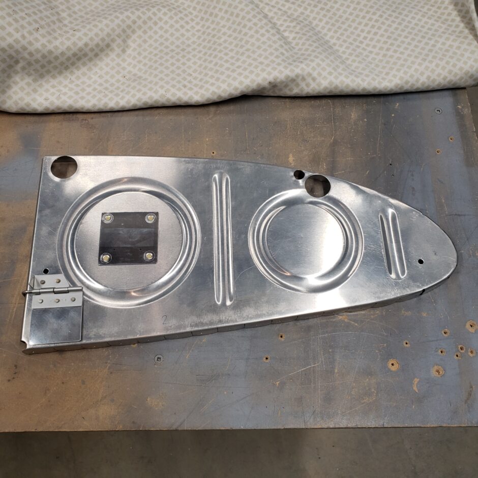
That’s all for today folks! Please comment. I love to hear from my readers. Thanks again for coming along for this ride, you make my work worthwhile.
Leave a Reply