While I’m still awaiting my new rivet sets that I need to complete riveting the horizontal stabilizer, I thought that now would be a good time to get started on construction of the wings.
Before beginning on this task, if you’re considering this route, there are a few things you will need before starting out.
- Van’s RV-4 Wing Kit (see my post for what to add/remove)
- Van’s RV-4 wing construction drawings/plans (they come with the wing kit)
- Harmon Rocket II plans (available here).
- F1 Rocket plans.
As if that wasn’t enough, you will also need to spend a lot of time on Vince’s Rocket website gathering, reviewing and learning all about what is involved in building the F1 Rocket Sport Wings. Below are some of the most important links to help steer you in the right direction. The reason that this step is so important, is two-fold: First, the F1 Rocket is a different aircraft than the Harmon Rocket II, so some of the dimensions are going to be different and this needs to be identified on your HRII plans (so you don’t get screwed up). Secondly, some of the dimensions on the HRII plans are not accurate, so these too need to be corrected. Vince, has done a good job of highlighting these, and I’ll try to add to them, or identify if there are any errors.
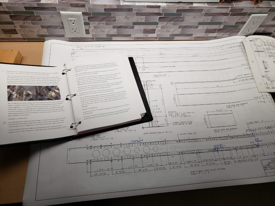
In the image below, you can see that I made a binder with Vince’s notes printed out. I’ve been using this as a step-by-step checklist to ensure that i make all the necessary changes to the HRII drawings and don’t miss anything. You can also see that I have been numbering the rivet holes for the spar.
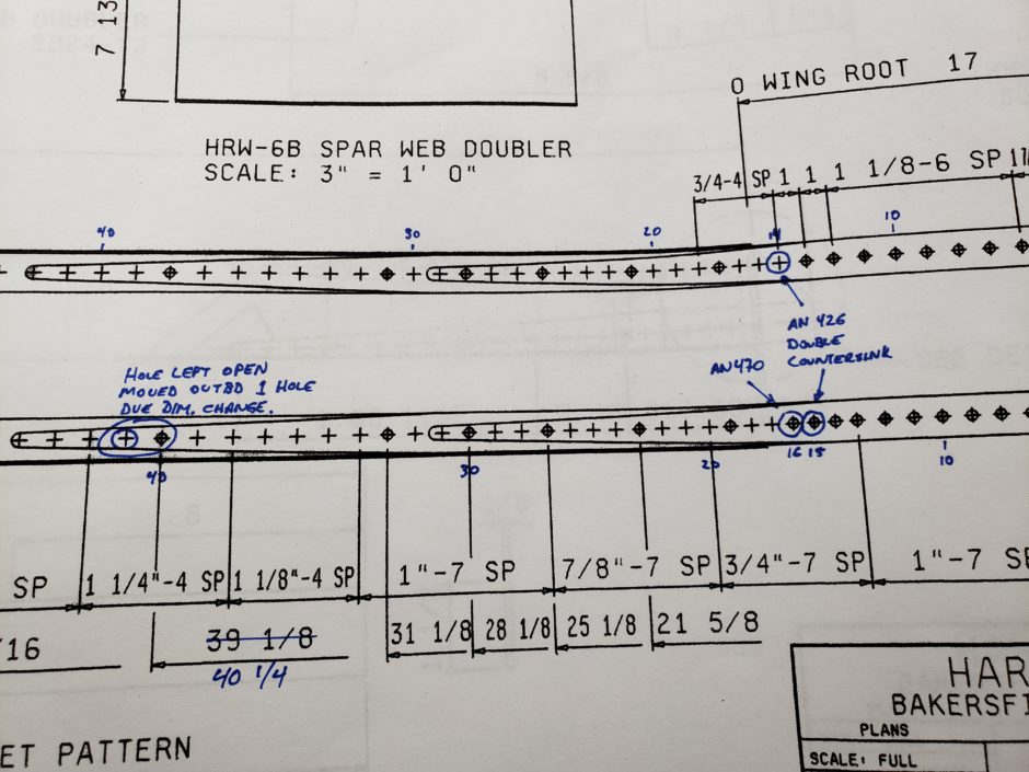
Here is a closer image of some of the annotations I have been making to the HRII drawings.
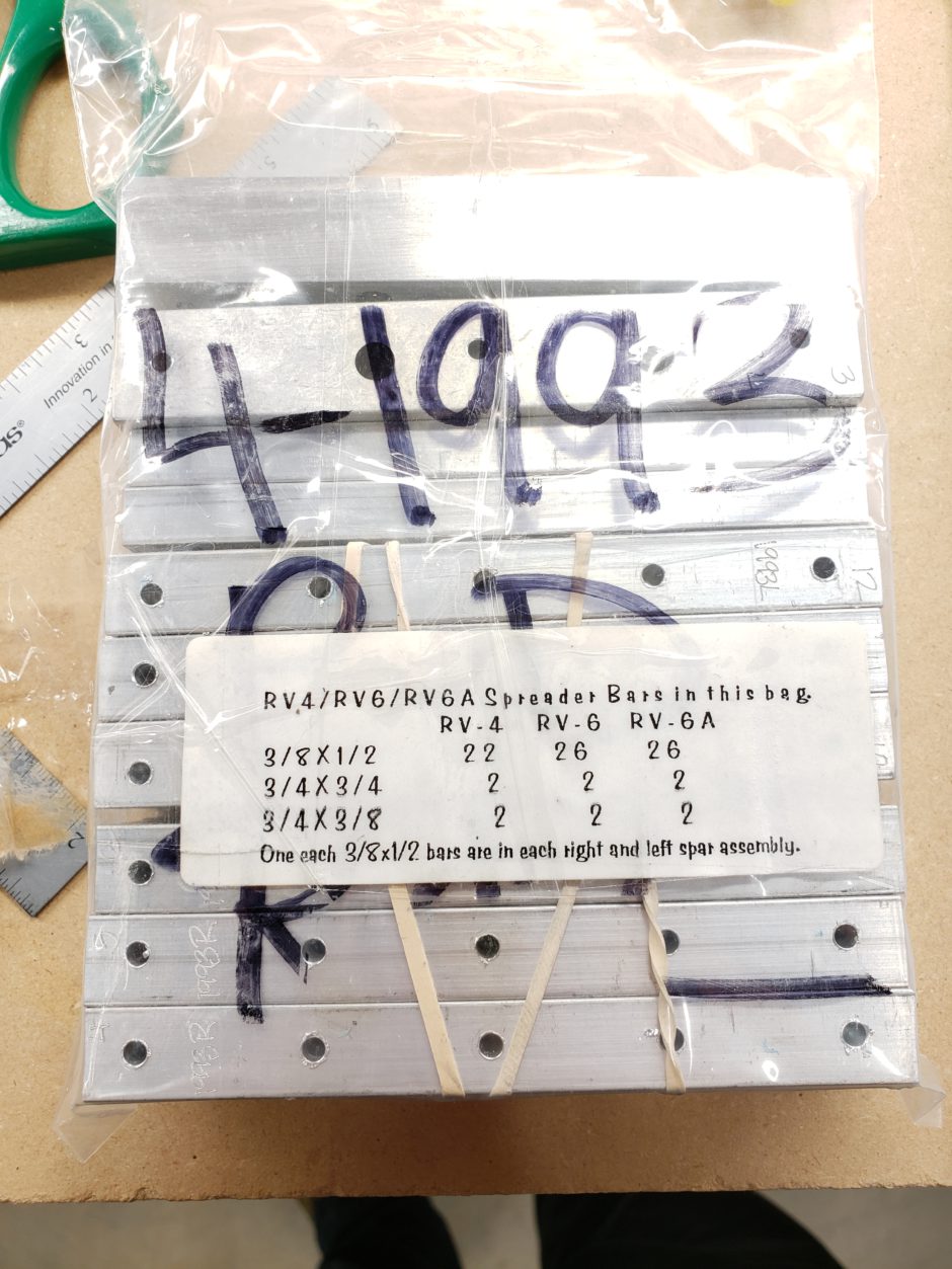
Another step in getting your bearings before you start into the wing build is to look for the bag of spar spacer blocks. My spar serial number is 4-1993. All of the spacer blocks are engraved by the factory, as well they are all predrilled when the wing spars were assembled in the factory jig. In the picture below you can see a few that are engraved. These are identified with an L or R at the end of the serial number to identify what spar they belong to. Also, there are 13 of these per wing and each is numbered 1 – 13, with 1 being at the root end and then working outboard.
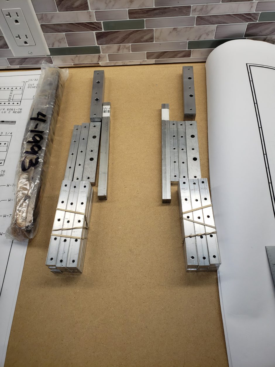
Below I have the spacer blocks separated into left and right piles. Slowly…I’m starting to be able to visualize what I’m looking at on the plan drawings.
The spars come somewhat temporarily assembled with 6 rivets and 4 bolts. The rivets are held on with little clips as shown below. The instructions call for you to put a piece of electrical tape below, then to work the edge of the clip up with a screwdriver, enough so you can cut them. Then you can just use some pliers to pull them up and off the rivets. The tape is there to just protect them spar web from damage while trying to left the edge of the clip.
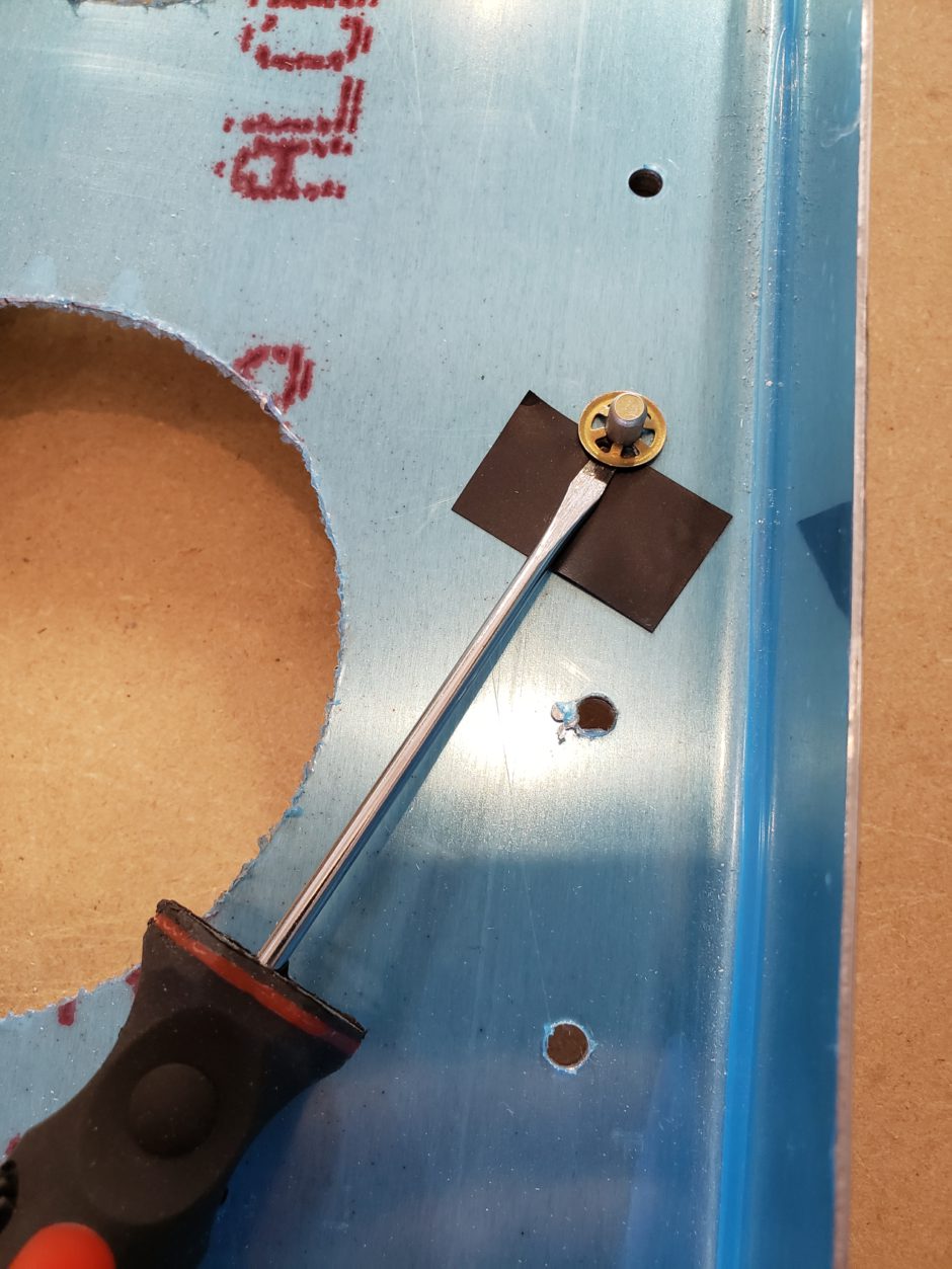
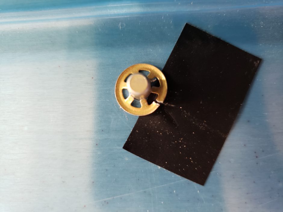
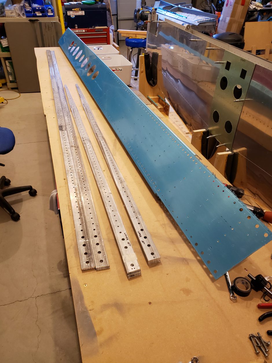
Once you get the rivets out, then the spar reinforcing beams come off and the spar can be disassembled into all the individual parts. Now the fun begins!
Please comment. I love to hear from my readers. Thanks again for coming along for this ride, you make my work worthwhile.
Leave a Reply