Continuing with the building up of the ailerons, I’m starting out today by trimming the aileron skin, as the ailerons on the F1 Rocket are 48 inches in length and are trimmed on the inboard side.

Here is a closer look at the trim line. 48 inches is the final dimension, and for now, I’m just going to trim about an inch larger. Better too much than not enough! You’ll note that outside of the 48 inch trim line is where one of the stiffener angles would be located on the RV-4 aileron. This extra length will eventually get trimmed off.
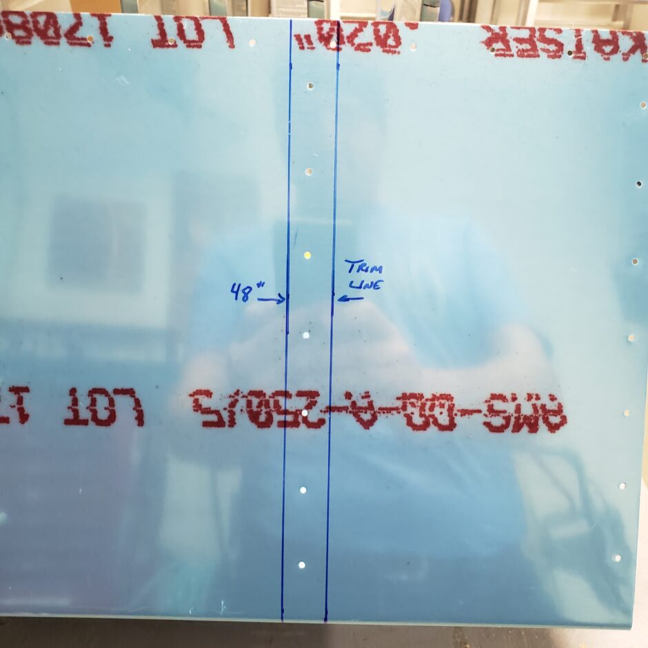
Cutting the aileron skin is really straight forward. No issues here.
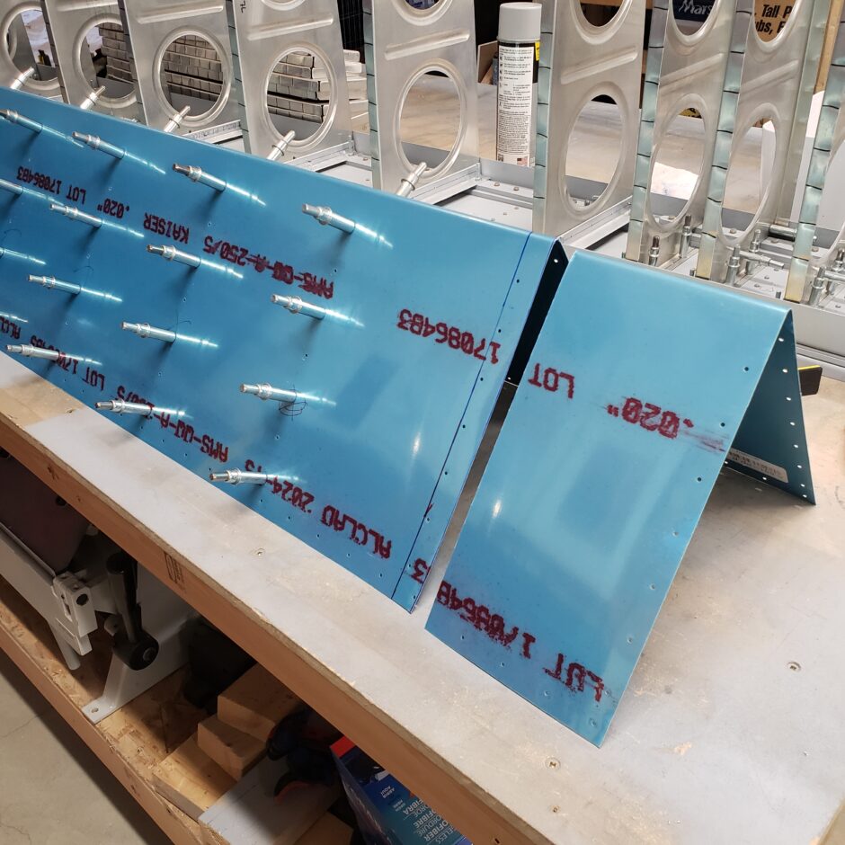
Inboard aileron – trailing edge ribs
With the aileron skin trimmed, I cleco’d the spar in place to begin locating the inboard end rib. Again, note that I’m about an inch inside the edge of the skin. Remember that this extra strip will trimmed flush with the end rib. I used cleco clamps to help hold the rib in place while I get it drilled to the skin. Also note that this rib is located in a section of the skin that isn’t pre-drilled. The holes on the edge that are pre-drilled are where an RV-4 aileron stiffener angle would have been located, but here we need to make some new holes to locate this rib.
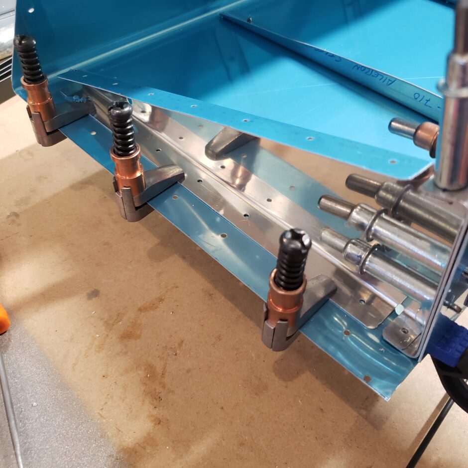
I thought that drilling the pre-drilled rib to the skin wouldn’t be too hard. As shown in the picture below, I planned to use the strap hole duplicator tool. Problem is…this tool won’t fit inside the flange because the pre-drilled holes are located too close to the rib to be able to use this tool.
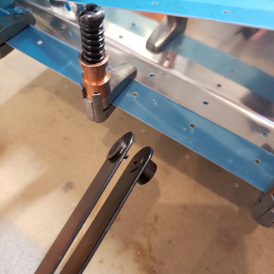
So, I’m going to have to make a drill template. I started out by marking the edge of the rib where it was clamped. Then I marked the location of each of the pre-drilled holes, removed the rib and drew a centerline to join all the identified hole locations.
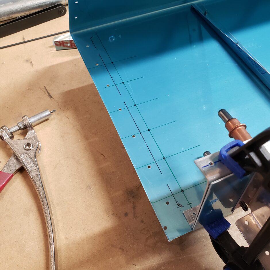
Next I cut a strip from some scrap aluminum to lay inside the rib flange. This will become my drill template for the skin. I can now back-drill the strip and the hole locations will be perfectly matched to the rib.
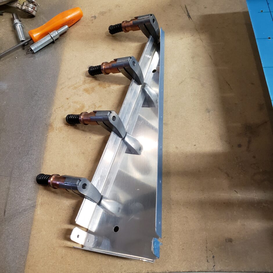
Here is the strip after being drilled to the rib.
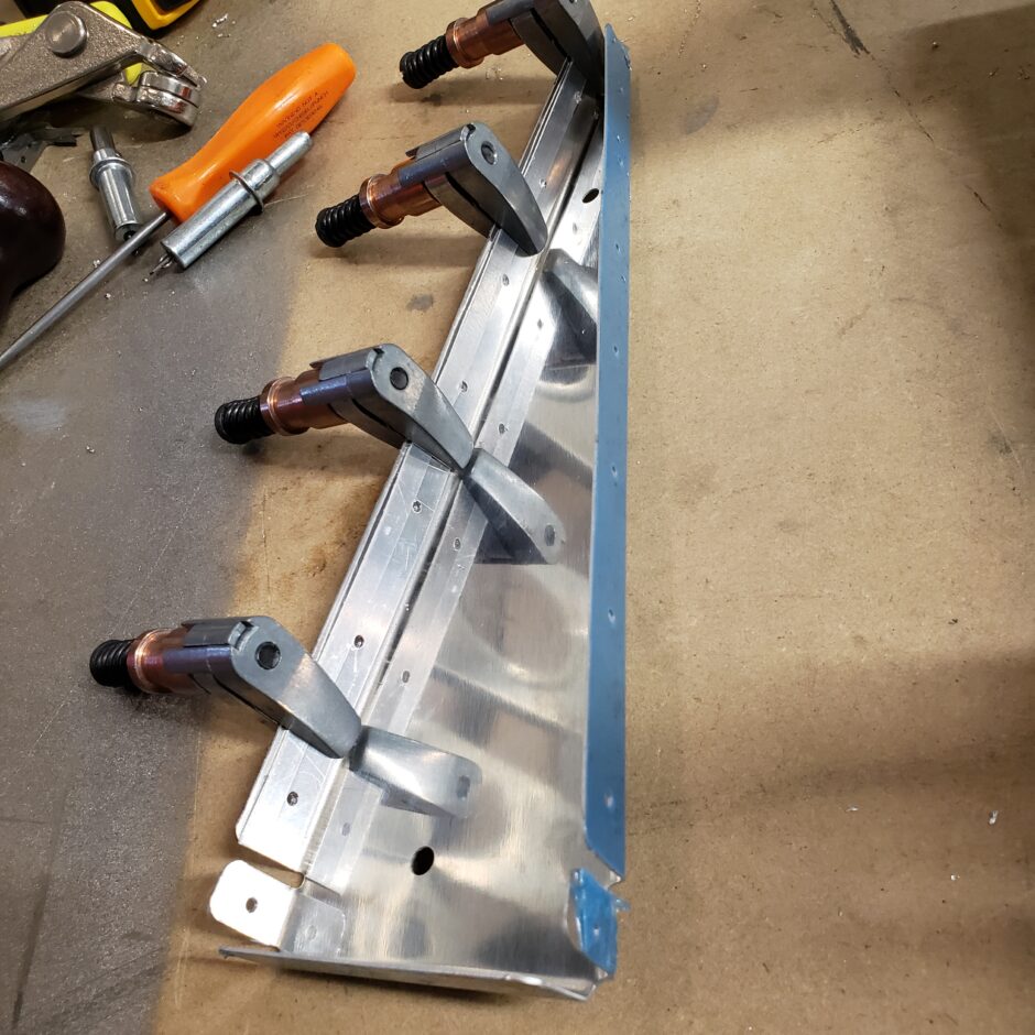
Now that I have a good (known) drill template, I just needed to get it aligned with the markings I made when I traced the rib. Alignment with the layout lines was also pretty easy, just line up the jig until you can see the dots for the drill holes when viewed through the template.
With the drill jig clamped to the skin, It was an easy exercise to just drill the holes.
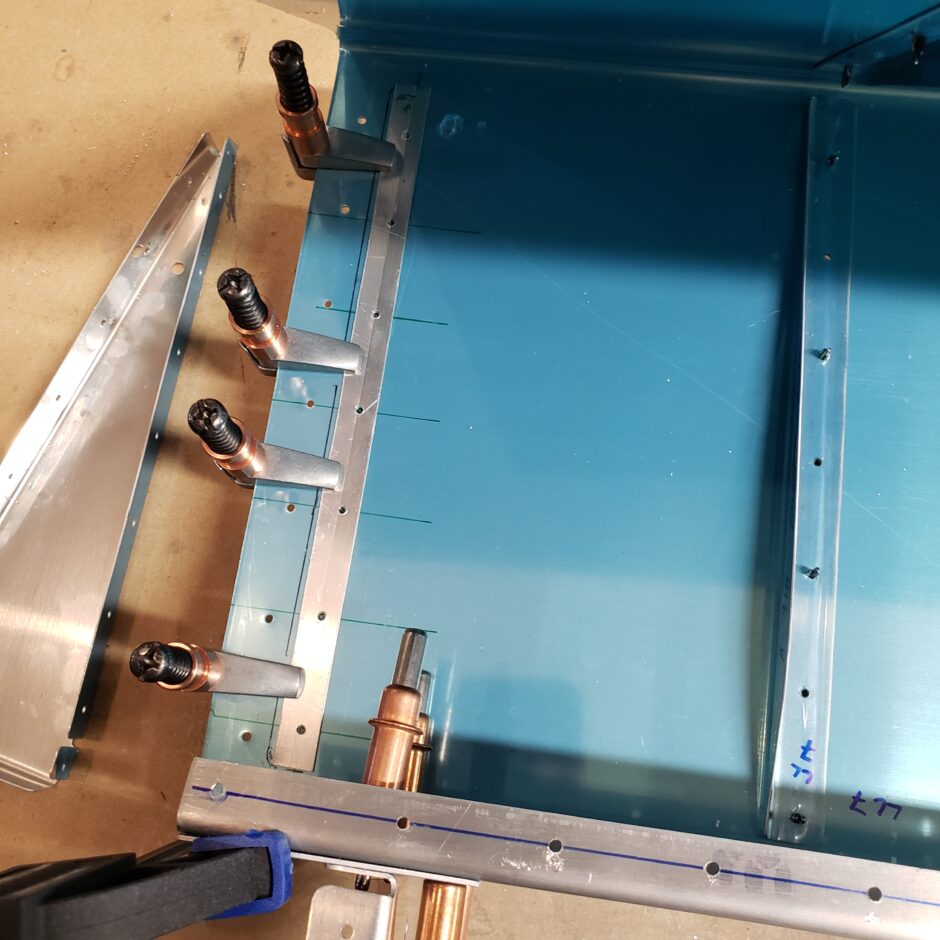

Using the template worked really well. The holes all lined up perfectly for the rib.
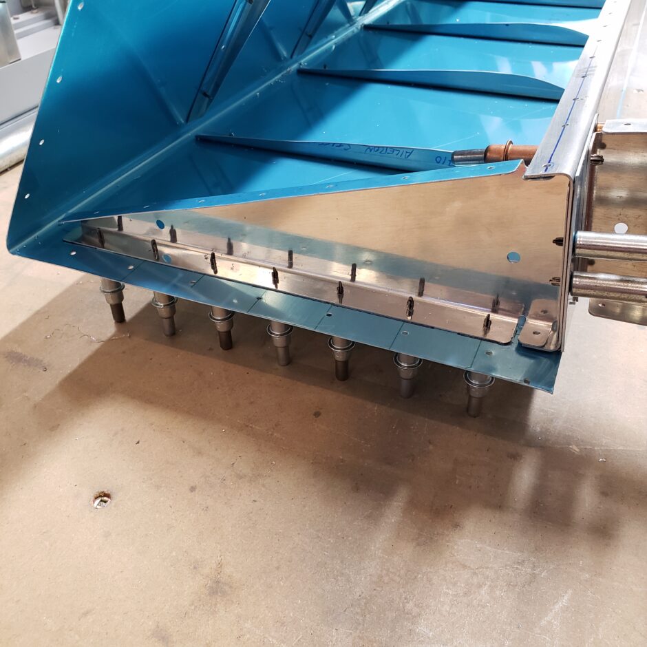
Flipping the aileron over to work on the upper surface, I’m doing the same thing again to mark the predrilled holes of the rib onto the skin, then I’ll make another template for this side.
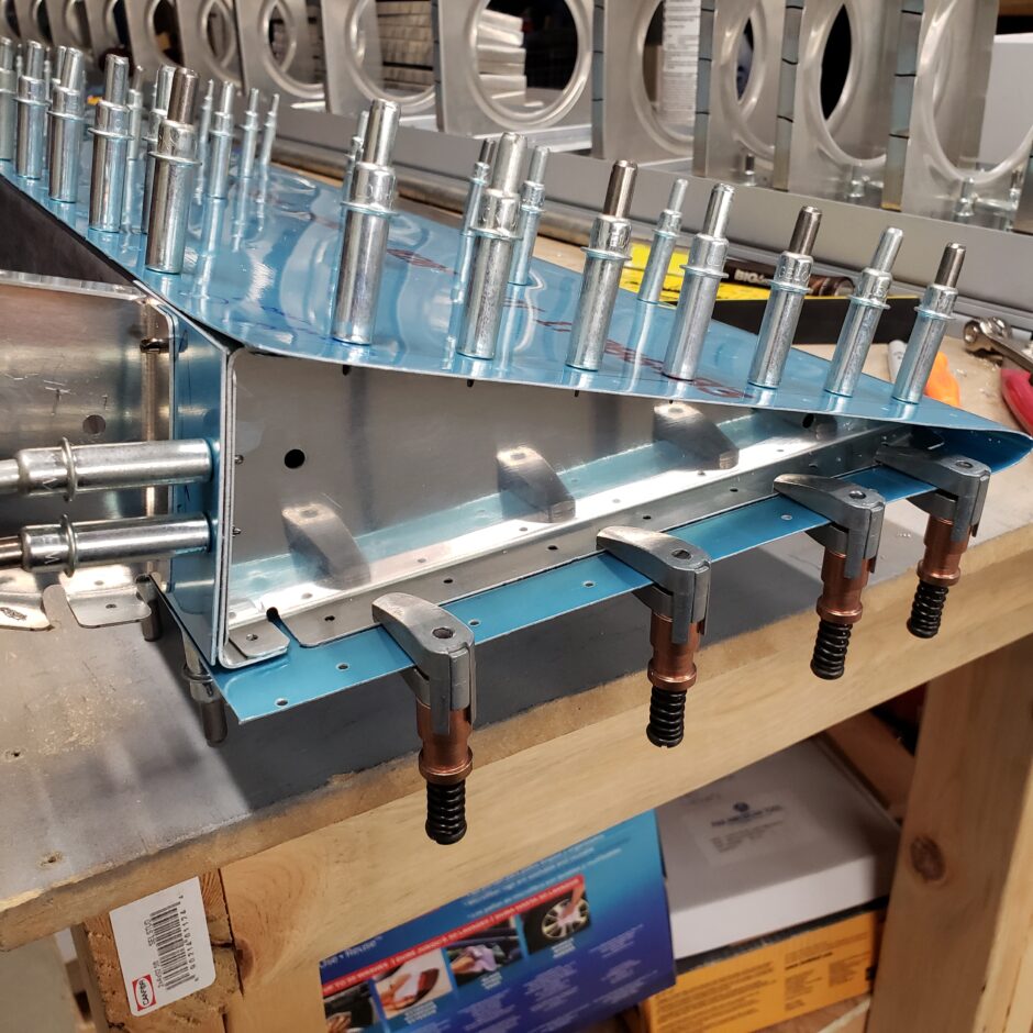
Once again, using a small piece of scrap, I quickly made another template.
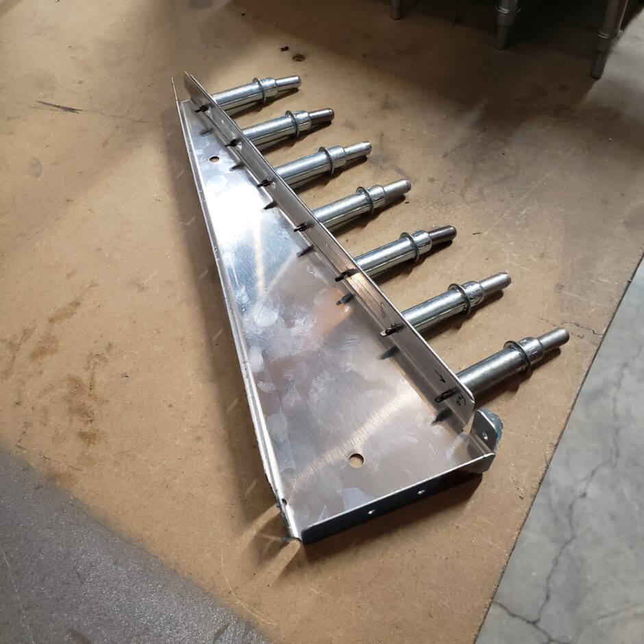
The template worked flawlessly on this side as well.
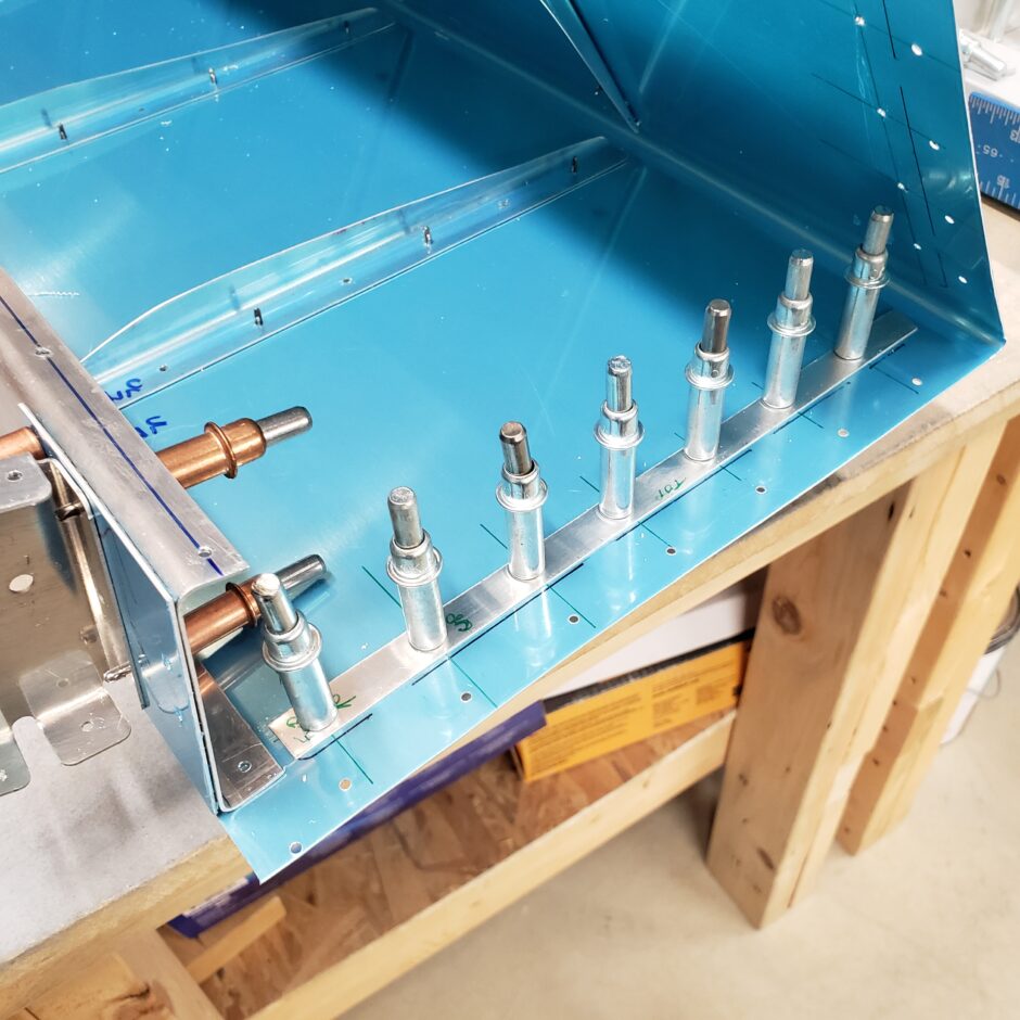
As you can see, by using templates the task of locating this rib and drilling new holes wasn’t all that tricky to do. The templates are definitely the way to go for this job.
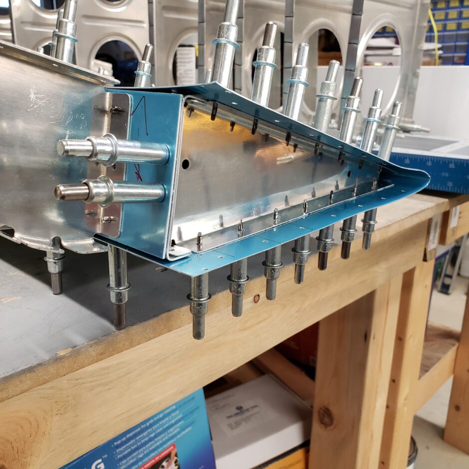
I finished off the skin by trimming off the excess material on the inboard edge. Then I was able to pull the plastic, ream the holes to the appropriate dimensions (these are all #40) and now I’m ready to prime this aft section of the aileron. Time to move on to finished up the leading edge of this aileron.

Aileron leading edge assembly
Moving on to the leading edge, the inboard end of the leading edge needs to be trimmed off to shorten the RV-4 aileron to the dimensions needed for the F1 assembly. Don’t throw that scrap piece away, as it’s perfect to make the drilling template for the end rib because it’s already pilot-drilled.
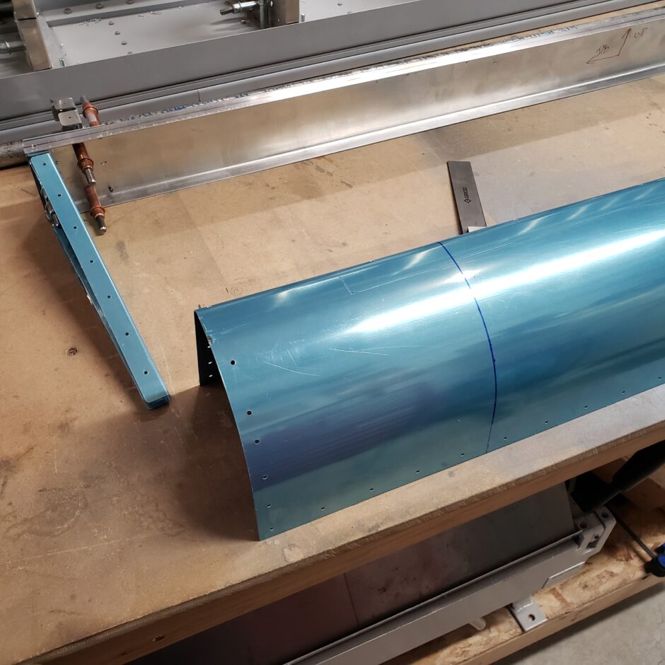
I started by trying to make the drill template with the metal strip on the inside of the skin…but in the end that didn’t work. As you’ll see further on, I had much better success with the template on the outside surface of the skin.
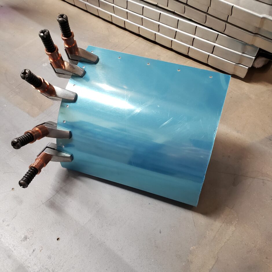
Now that I have the leading edge assembly together. You can see the end closest in the picture, is the inboard side of the leading edge skin that was trimmed down. The far end (outboard) was easy to drill as the skin is pre-drilled, and the rib is somewhat pre-drilled. So the outer end assembles pretty quickly.

Here is a closer view of the inboard end that needs to be drilled. Again, this is a perfect place to use a drill template because I can overlay the scrap template material directly over the pre-drilled end that I cut off. Then after the template is drilled, I can lay it directly on top of the skin here for a perfect match. This is why my initial attempt at the drill template on the inside of the skin didn’t work. Once that would be placed on the outside, the holes would be slightly off. This way (on the outside of the skin) it’s a perfect match.
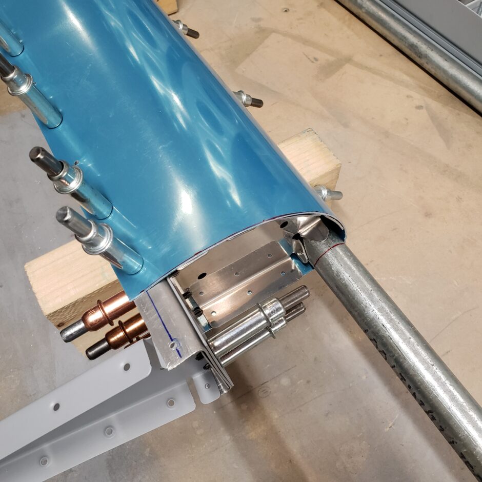
Here is a closer picture of the outboard end of the aileron. As it’s all pre-drilled and no modifications made here, this end is quickly assembled.

Moving back to the inboard end, the pipe will have to be trimmed to final length, along with drilling the rib to the skin. In the picture below, you can see that I now am working with the drill template starting on the outer surface of the leading edge skin.
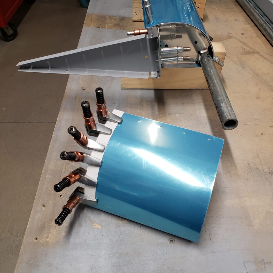
The picture below is a good depiction of the nose rib, showing details of the holes that come pre-drilled (in the RV-4 kit) and the undrilled flanges.
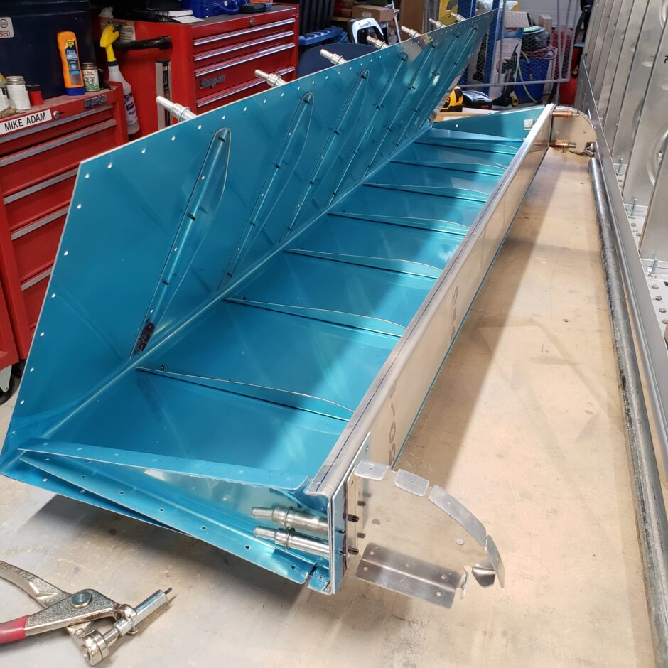
Looking closer at the end rib, you can see that some of the rib flanges are pre-drilled. These were drilled first using the strap duplicator. The others I’ll finish drilling by using the template. Starting with the pre-drilled flanges greatly helped to align the drill template. You’ll need to keep this whole assembly tightly clamped to be able to get accurate holes drilled because the skin doesn’t really sit tight to the rib.
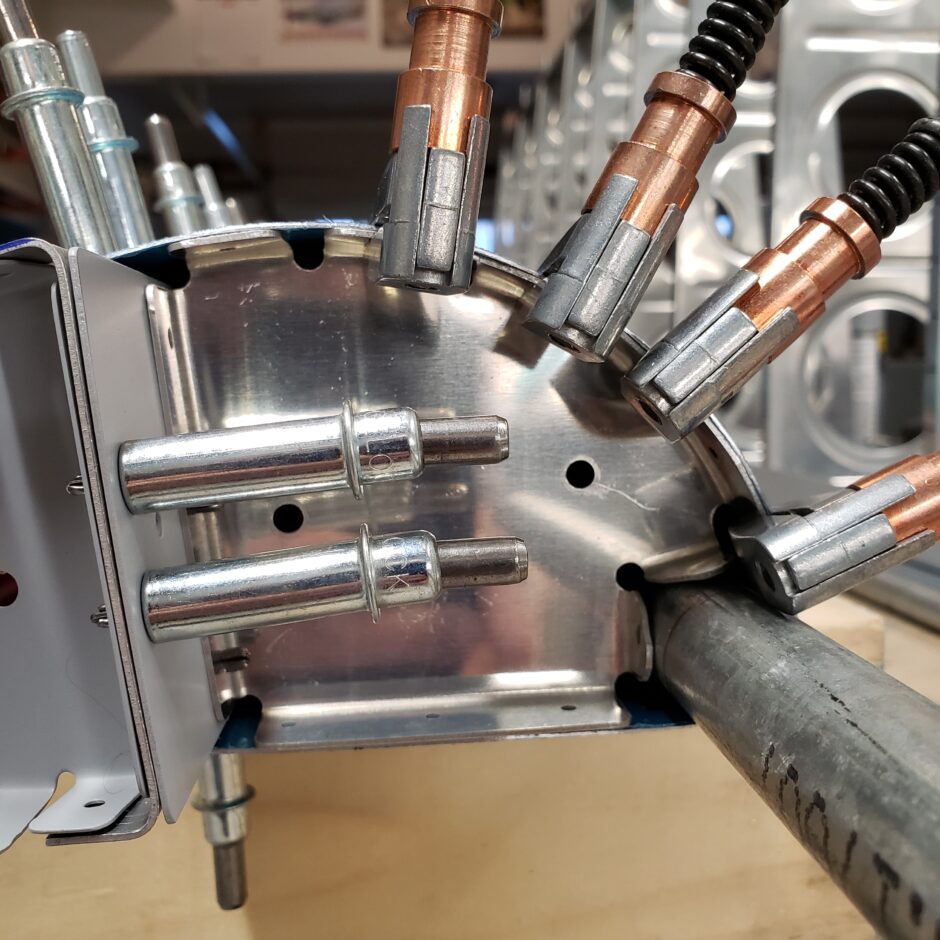
Then I used the strap duplicator to pickup the first hole to be drilled in the rib.
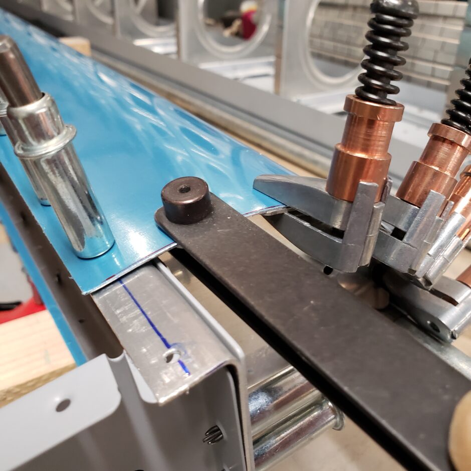
With the first 2 holes of the upper leading edge match drilled to the pre-existing holes in the rib, I was able to get the drilling template located once I removed the rib to make it easier to work with. Once the rib is all drilled, I put it back on the aileron, and finished match drilling the skin with the strap duplicator, and then drilled the 3 holes on the lower surface.
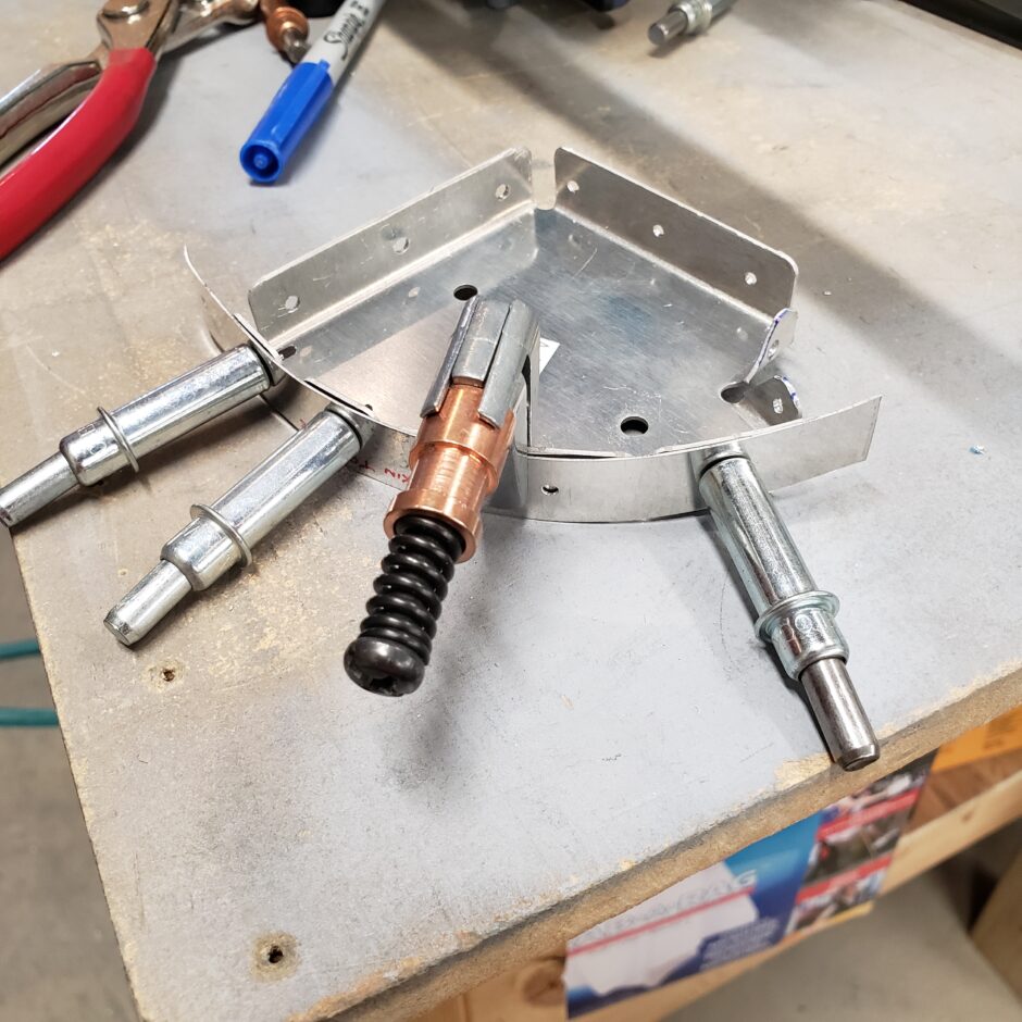
Then with the rib installed back in the assembly, it was easy to again use the strap duplicator to transfer the pre-drilled holes of the rib to the undrilled skin.
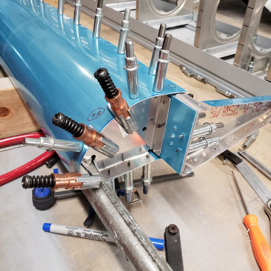
In the picture below…well, even I screw up once in a while (LOL!). I don’t know what I was thinking but this is the result of a momentary lapse in attention. Like always, when things seem to be going too smoothly…you’re going to screw up something. And as you can see I totally missed the middle hole. Not the end of the world, I’ll just add a double to this flange when I rivet it together. I’m not up for ordering another rib and yet another leading edge skin at this point.
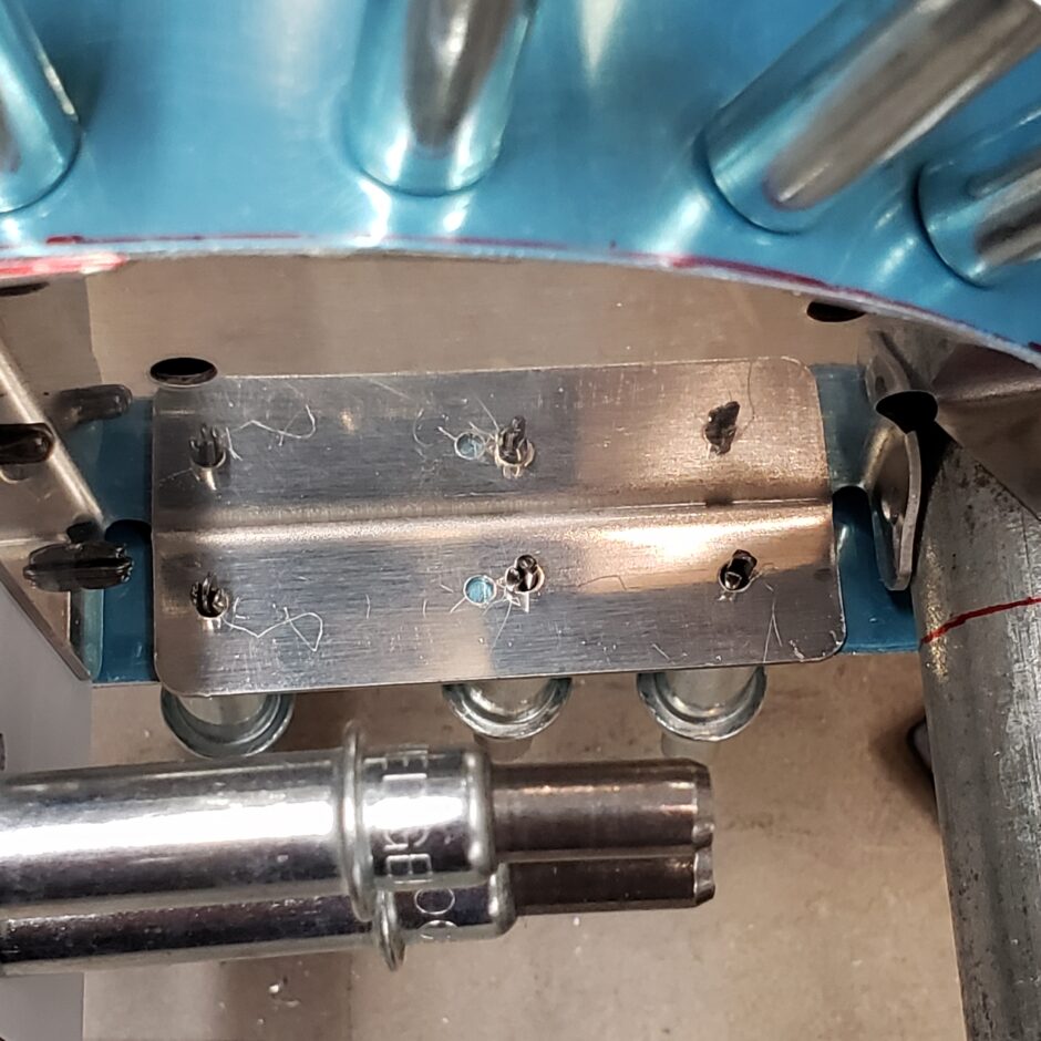
This now completes pre-drilling the leading edge end ribs to the leading edge skin. The next step of the process is an important one, which is drilling the aileron skins to the spar in the area of the inboard leading edge rib.
Important cautionary note here!!!
DO NOT DRILL the hole in the spar that is pre-drilled (the hole in the corner of the leading edge skin as shown below). This will be pre-drilled at a later time. I have explained my rationale for this in a separate section of the post below.
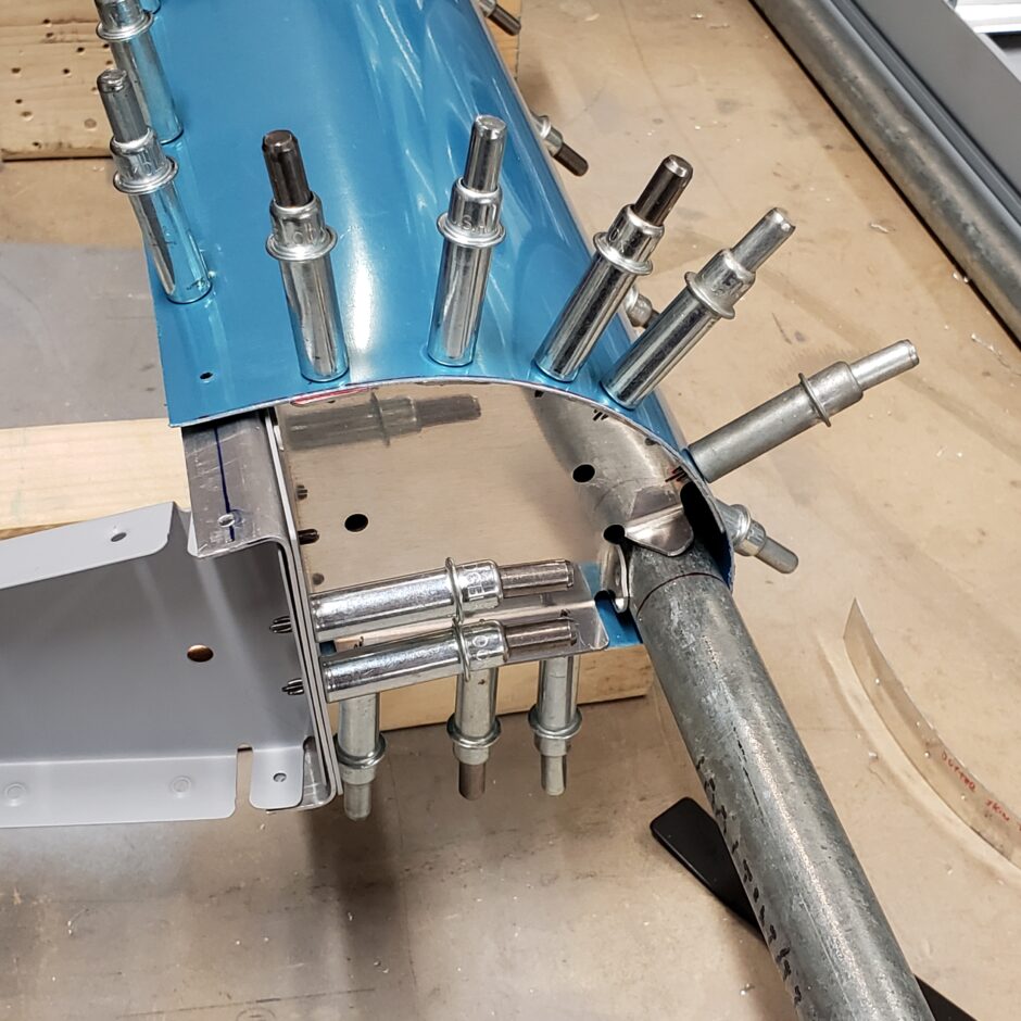
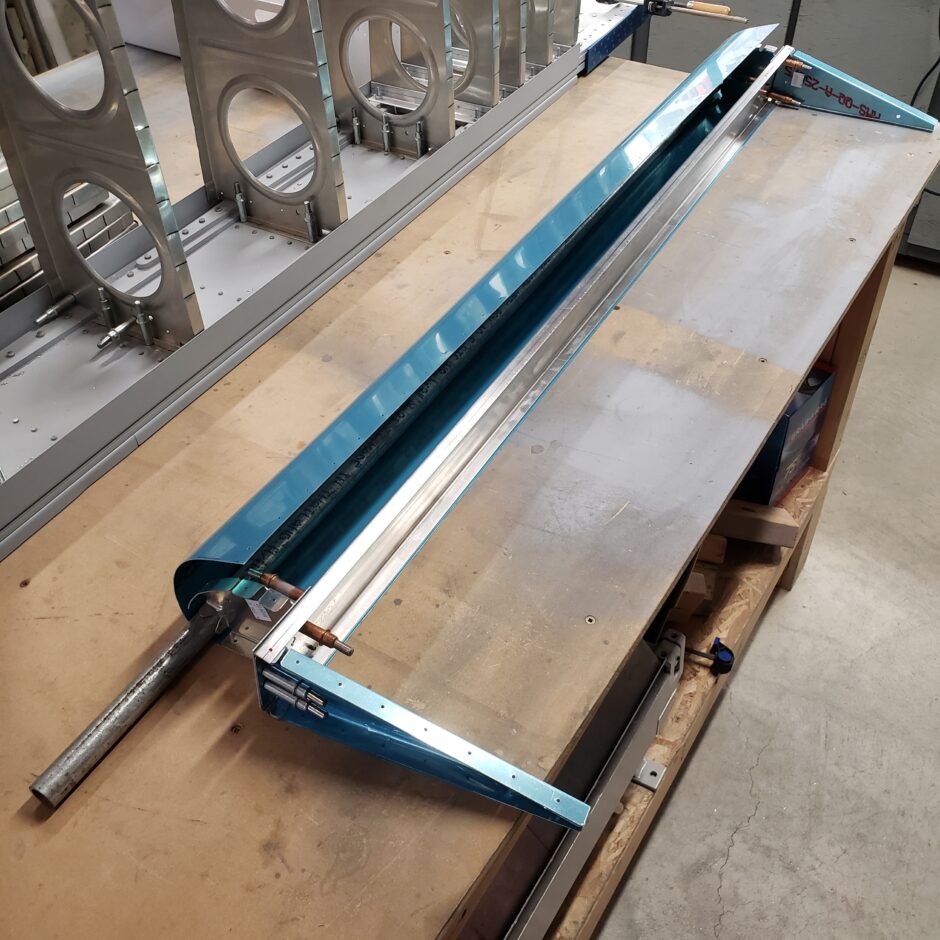
At this point you can see that the leading edge is pretty much all built up at this point. I just need to trim the balance weight pipe, and drill the tabs that attach the pipe to the leading edge rib.

Here is another picture of where you can see how much is trimmed off to account for the F1’s shortened wingspan.
Drilling those tabs!
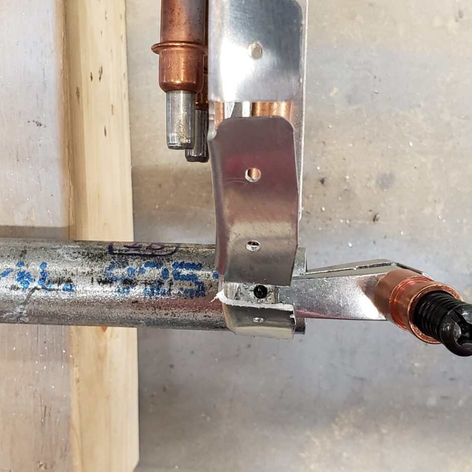
Next up, I’m going to tackle drilling the second tab (or flange) of the rib that is riveted to the balance weight pipe. As you can see, I have the rib pre-drilled. Now I need to transfer that hole to the pipe.
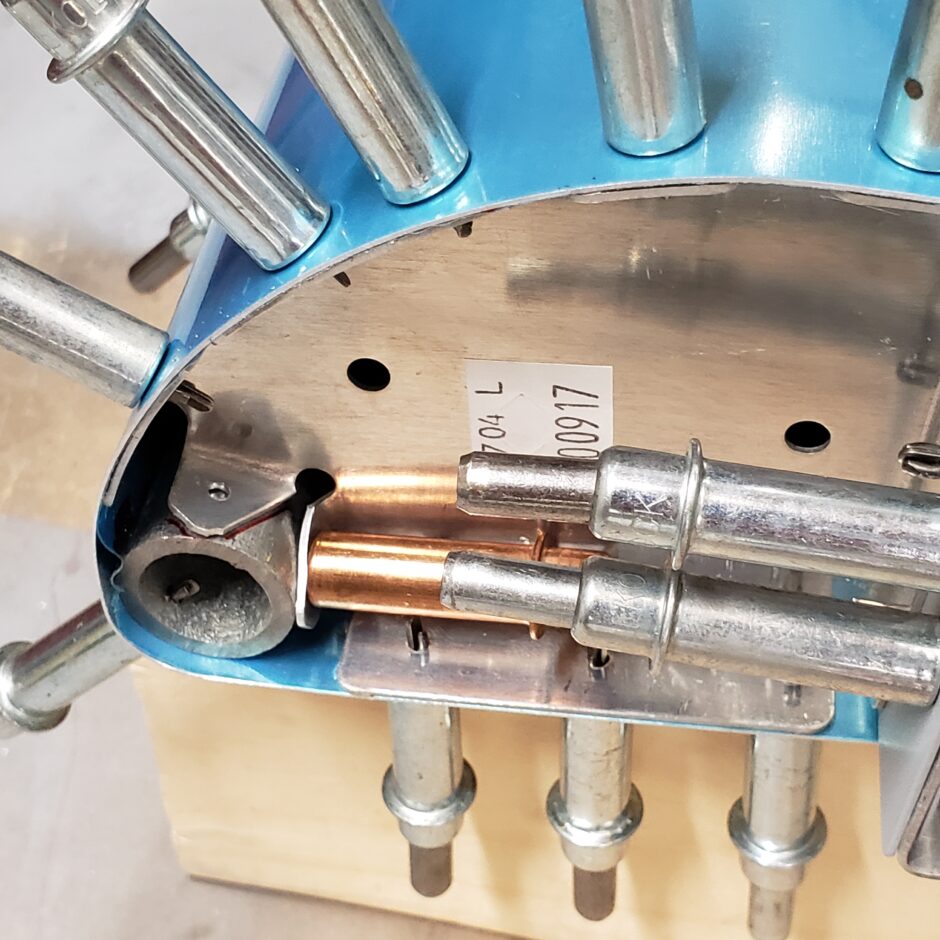
The way I was able to figure out how to drill this tab was by trimming some of the rib flanges to permit to enough access to get a drill bit to fit vertically. There is sufficient edge distance on this rib to be able to time a bit off as shown below.
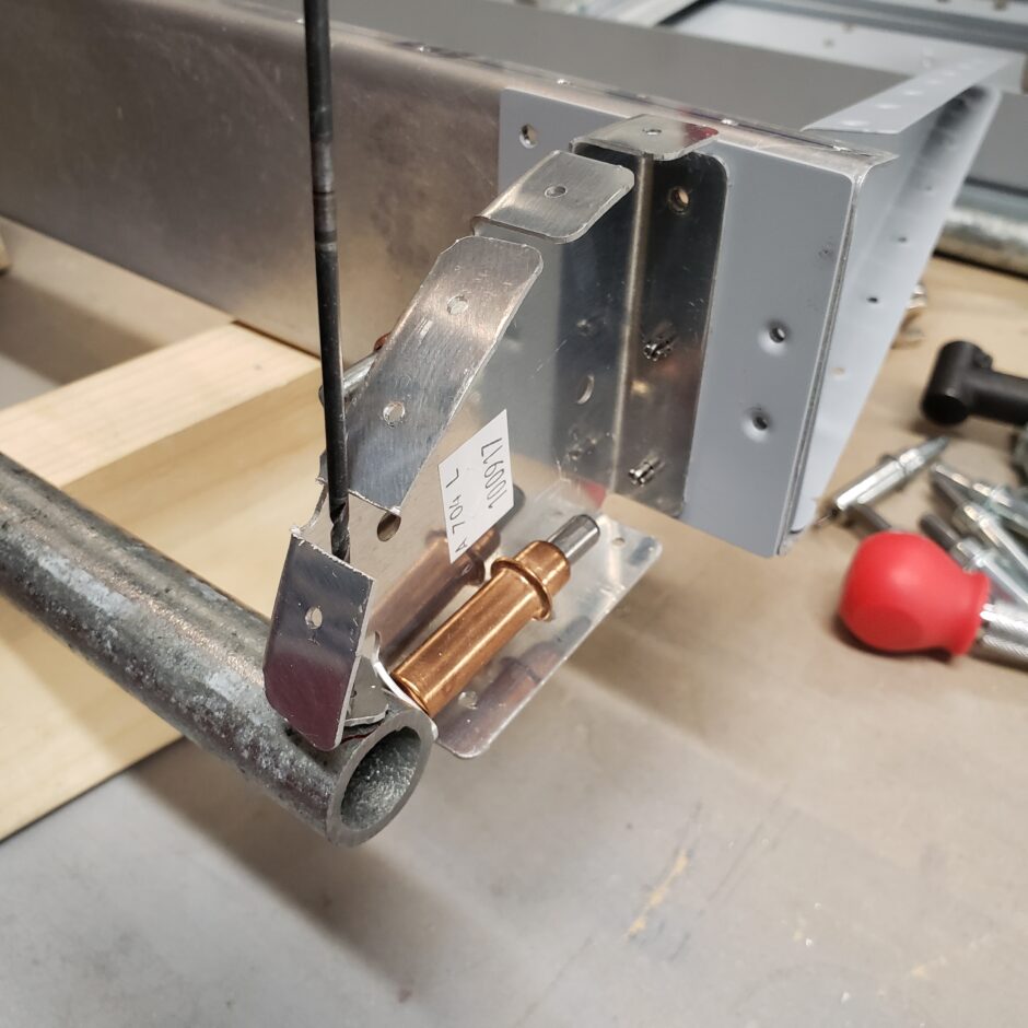
Here’s a side profile and you’ll see that you need to trim off a little bit from both of the tabs to get the drill bit angle to fit vertically.
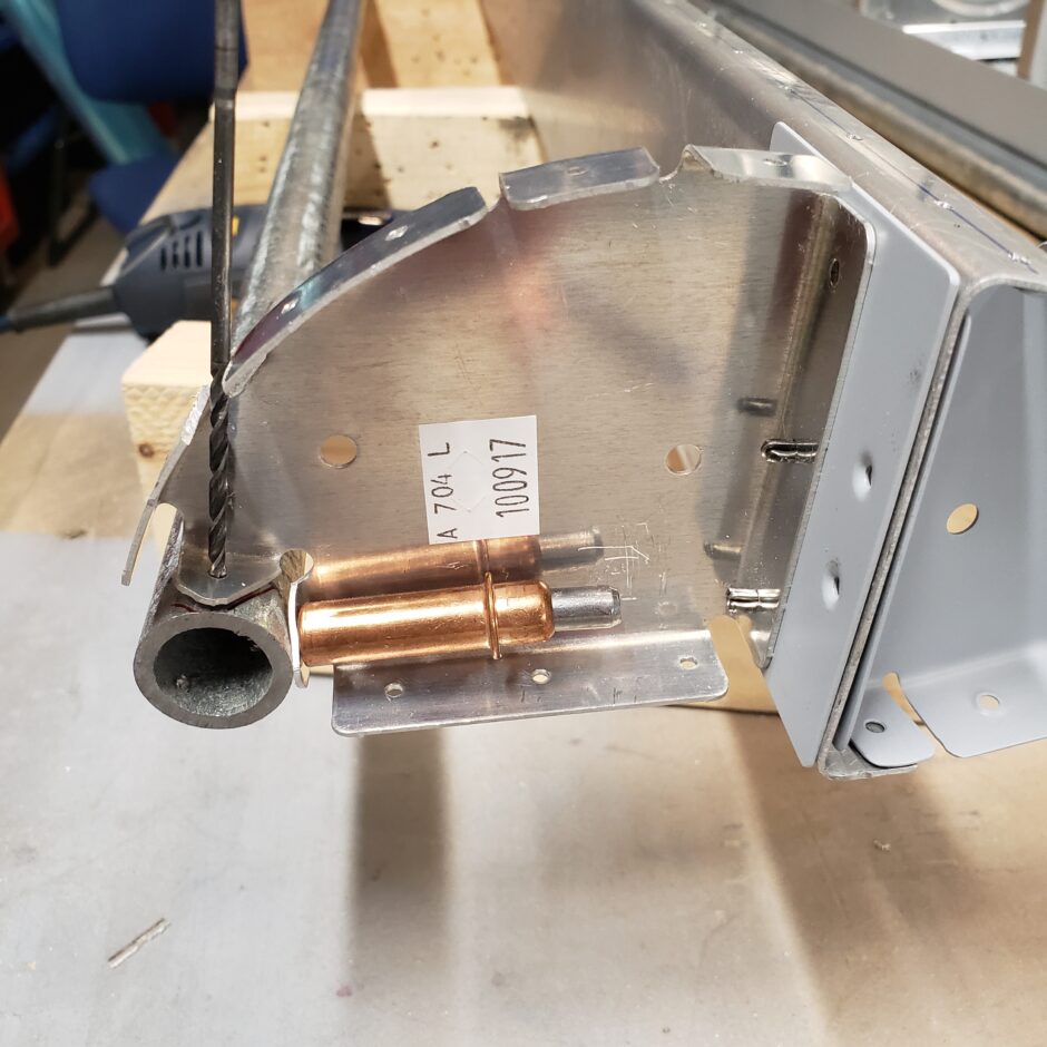
Below, the hole has been drilled and as viewed from the top down, you can see another angle of why you need to trim off a bit of both sides of the flange to crate the access needed to drill this hole.

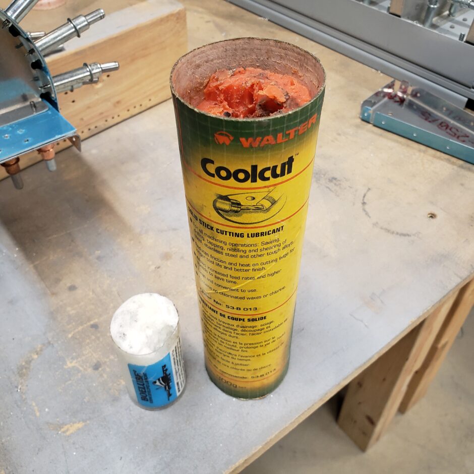
I found that drilling the balance weight pipe wasn’t the easiest. I tried to use a tooling cutting lubricant. It was ok…but then I switched to the Boelube and the cutting performance dramatically improved. I don’t know what in that stuff, but it significantly helped with drilling.
Balance weight pipe details
Now that the aileron leading edge is assembled on both ends and to the spar, the next step is to finish drilling the balance weight pipe to the leading edge skin. For this, I positioned the assembly to sit leading edge up for better access to the working surface. Then I began by drilling one hole in the middle to get it cleco’d. In the picture below, you can see that the leading edge skin is pre-drilled so that makes it easy to proceed.
In this area I felt it was best to start by drilling the middle, then to keep drilling the middle of each side and splitting the difference until the leading edge was completely drilled. I think this helps to distribute any movement along the skin as you drill.

Here’s a picture after I got all the leading edge holes drilled.
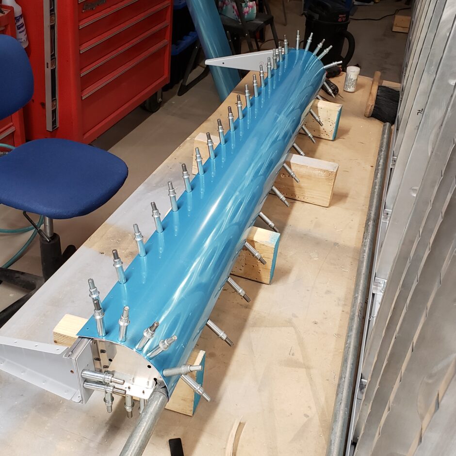
All the rivets along the leading edge are CS4-4 pulled rivets, which are countersunk, therefore the leading edge skin needs to be dimpled and the balance pipe needs to be countersunk to accept the dimples.
To countersink the balance weight pipe, I clamped it to the workbench and used a caged countersink with my cordless drill. It’s a bit of trial and error until you can get it just right. Slow and steady makes the best progress here. I also used a small piece of scrap material that was dimpled for the CS4-4 rivets, and used this to check the countersink depth because checking it with the leading edge skin is not really practical.
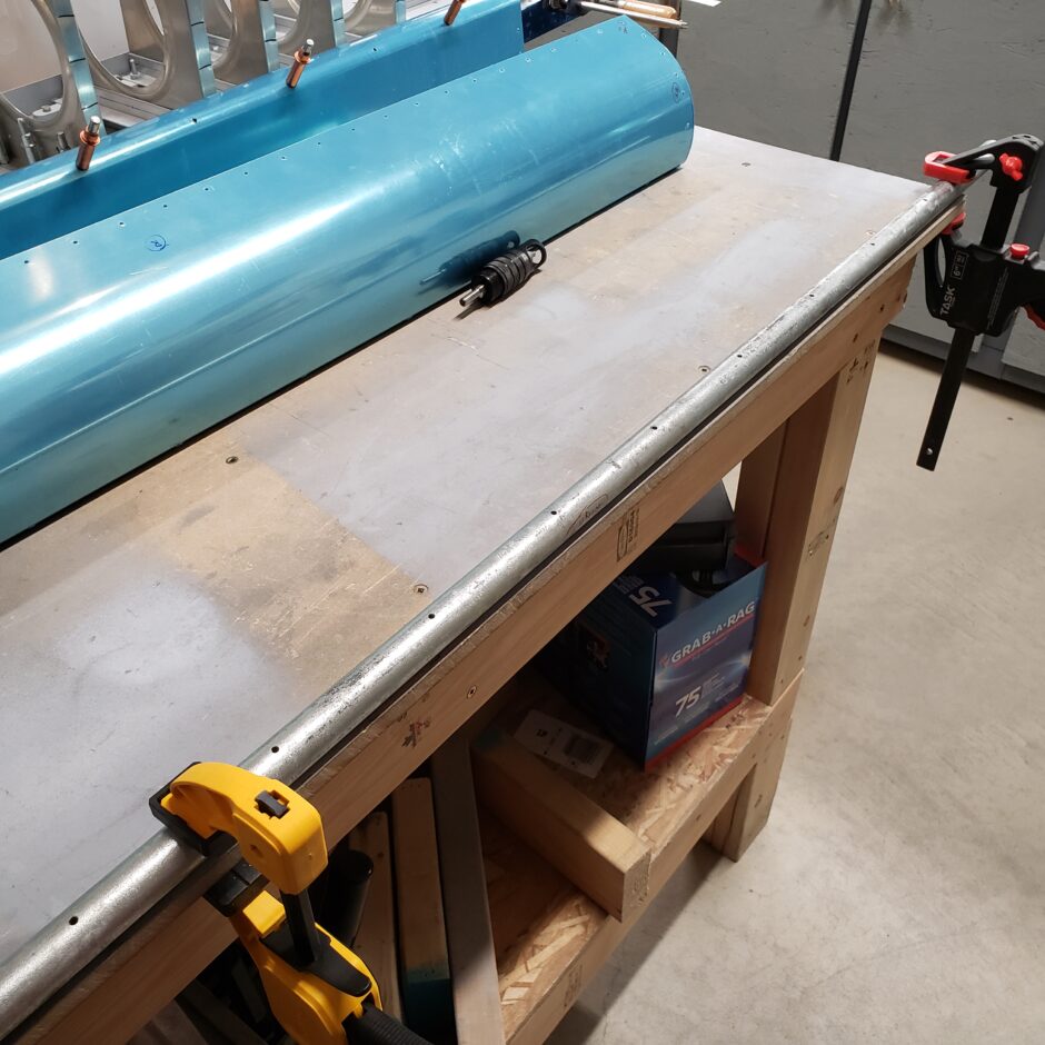
I struggled a bit when it came to how to dimple the leading edge holes. It took a bit before I was able to scrounge through the toolboxes to see what I could come up with to form these dimples. What I found was a plunger shaft out of my old pneumatic squeezer. This worked well because I was able to put the dimple die in. Next I put the balance pipe back into the leading edge skin assembly. As the pipe is already countersunk, I’ll use the plunger and dimple die with a rubber mallet to manually form the dimples in-situ.
Another consideration here is to find a way to support the back side of the pipe so that you can beat on it with the mallet and the leading edge assembly still remains supported. This will definitely help provide better results.
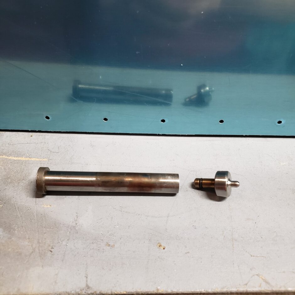
This dimple forming method worked quite well. Again, slow and steady work here is the key. It won’t take long to figure out just how much or how little force is required to form these dimples.

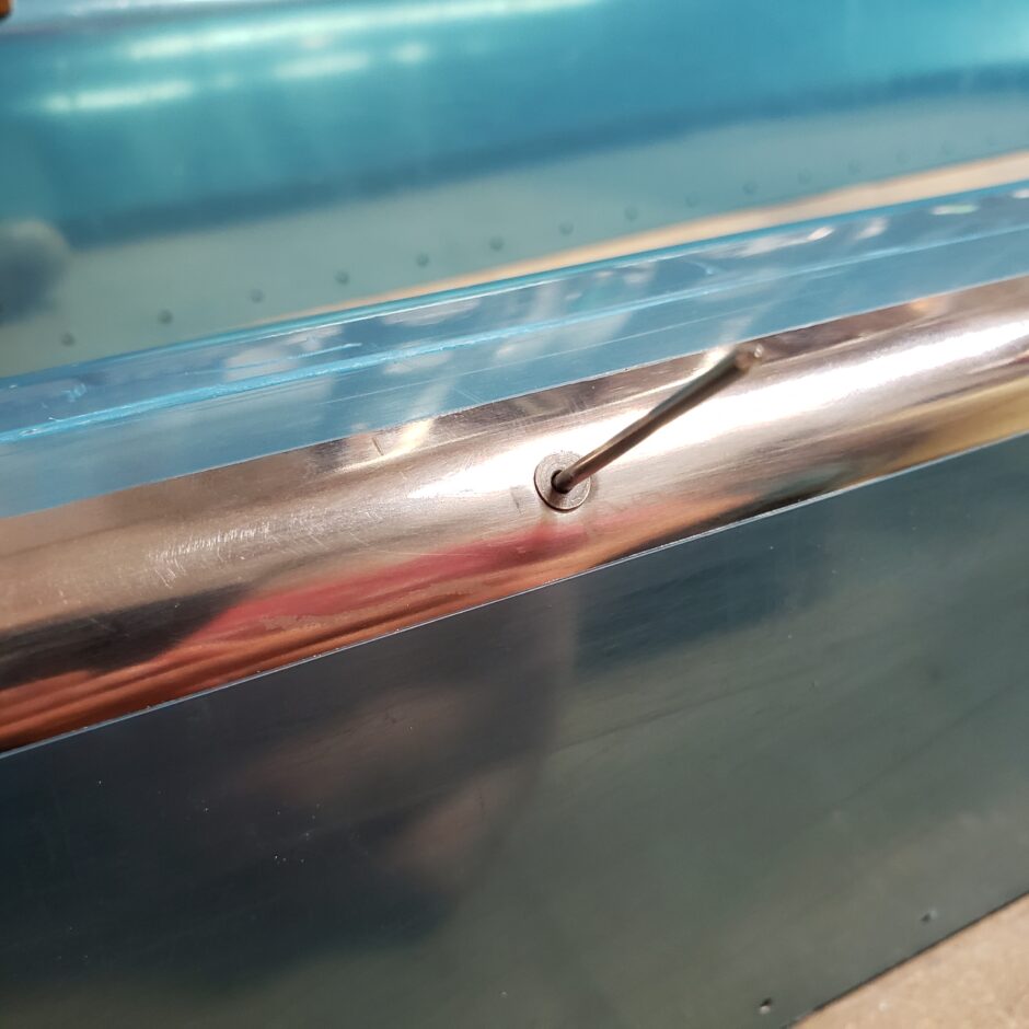
After each dimple was formed, I checked the work by fitting a CS4-4 rivet to make sure that the dimple was properly formed. The rivet worked as a simple go-no-go gauge.
No Drill Holes Explained
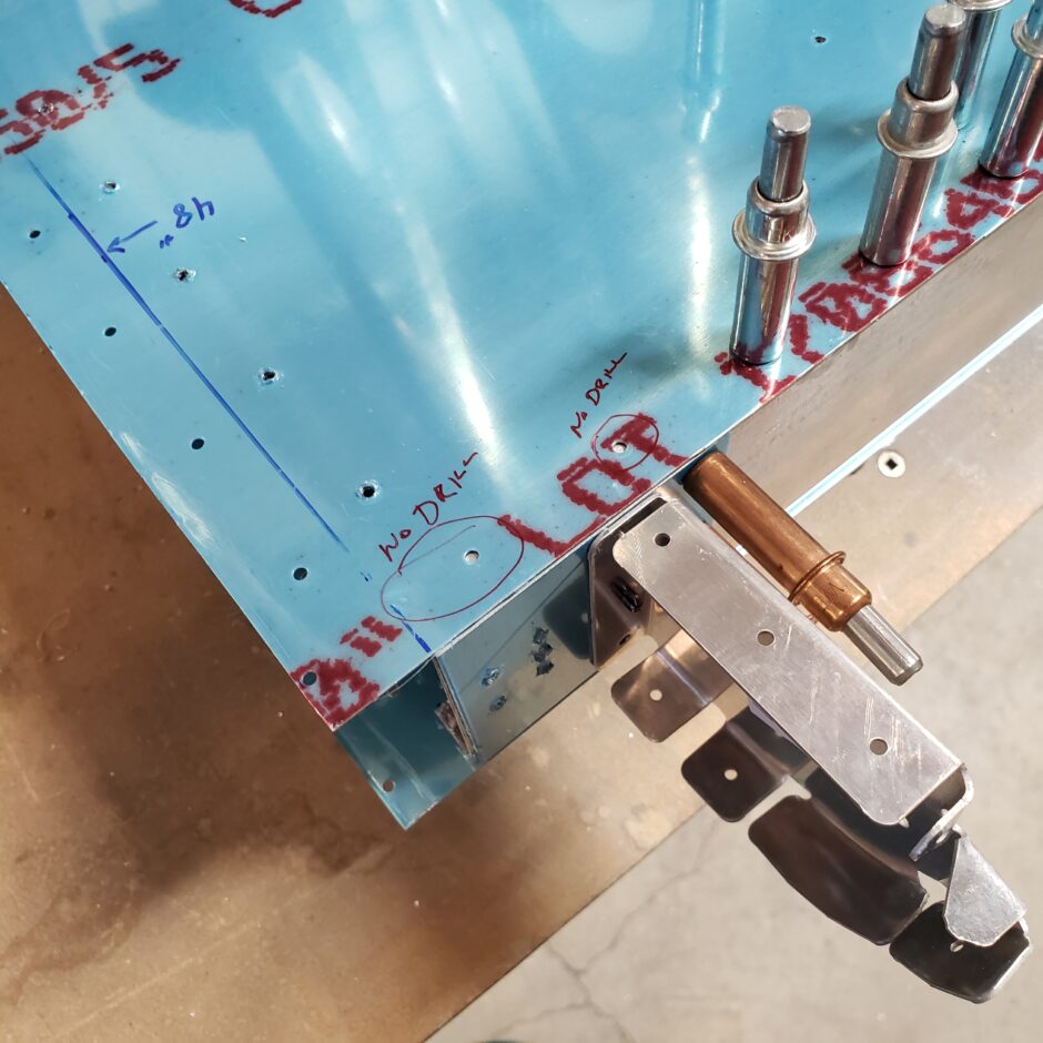
Again, as described above, there are a couple holes left undrilled when installing the inboard leading edge rib. This doesn’t apply to the outboard rib as it’s all predrilled (at least on the RV-4 kit that I’m starting with). But on the inboard side, as you need to relocate both the leading edge rib and trailing edge rib into an area that is undrilled. With this relocation of the parts, some of the pre-drilled holes don’t line up properly. As identified below, you can see I have the 2 inboard spar rivet holes circled (upper surface) for no drilling at this time.
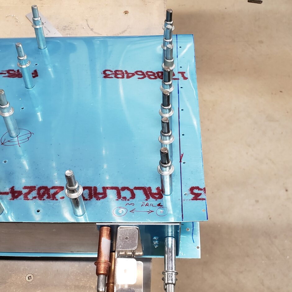
When you look closely at the picture above, if you follow the line of clecos down from the from the trailing edge (top of the picture) to the spar. You will note that this line of rivets does not align with the outboard pre-drilled hole of the trailing edge skin on the spar. Remember, that the trailing edge rib has a small tab to account for the thickness of the spar cap, as shown in the picture below. And these have already been match drilled to the spar.
Additionally in the picture above, when make the same visualization for the row of rivets on the leading edge rib and it’s row of rivets, it too doesn’t align with the pre-drilled hole.
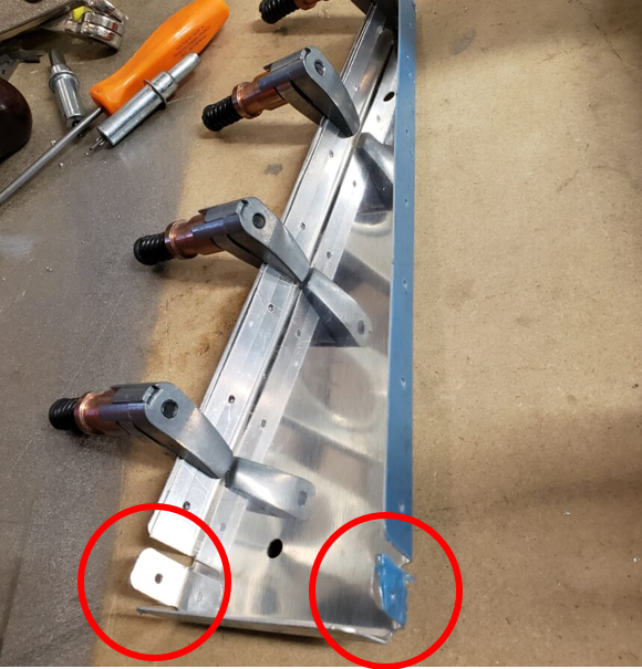
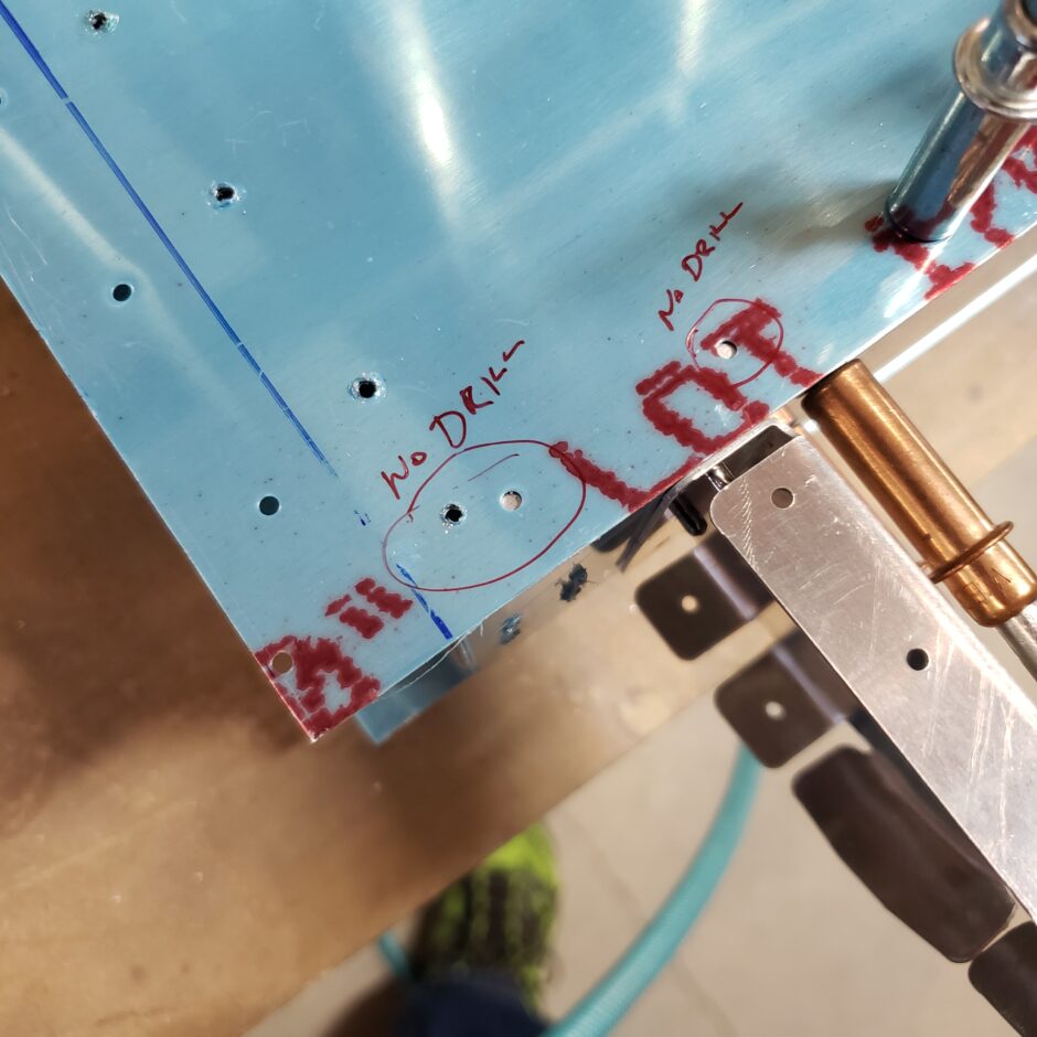
The picture below, shows the bottom of the aileron with the no-drill holes identified.
As the spar has already been pre-drilled to match the tabs of the trailing edge rib (at the spar cap), I used the strap duplicator to further match drill these holes to the trailing edge skin…because that’s just where the holes need to go. There isn’t much choice in that matter.
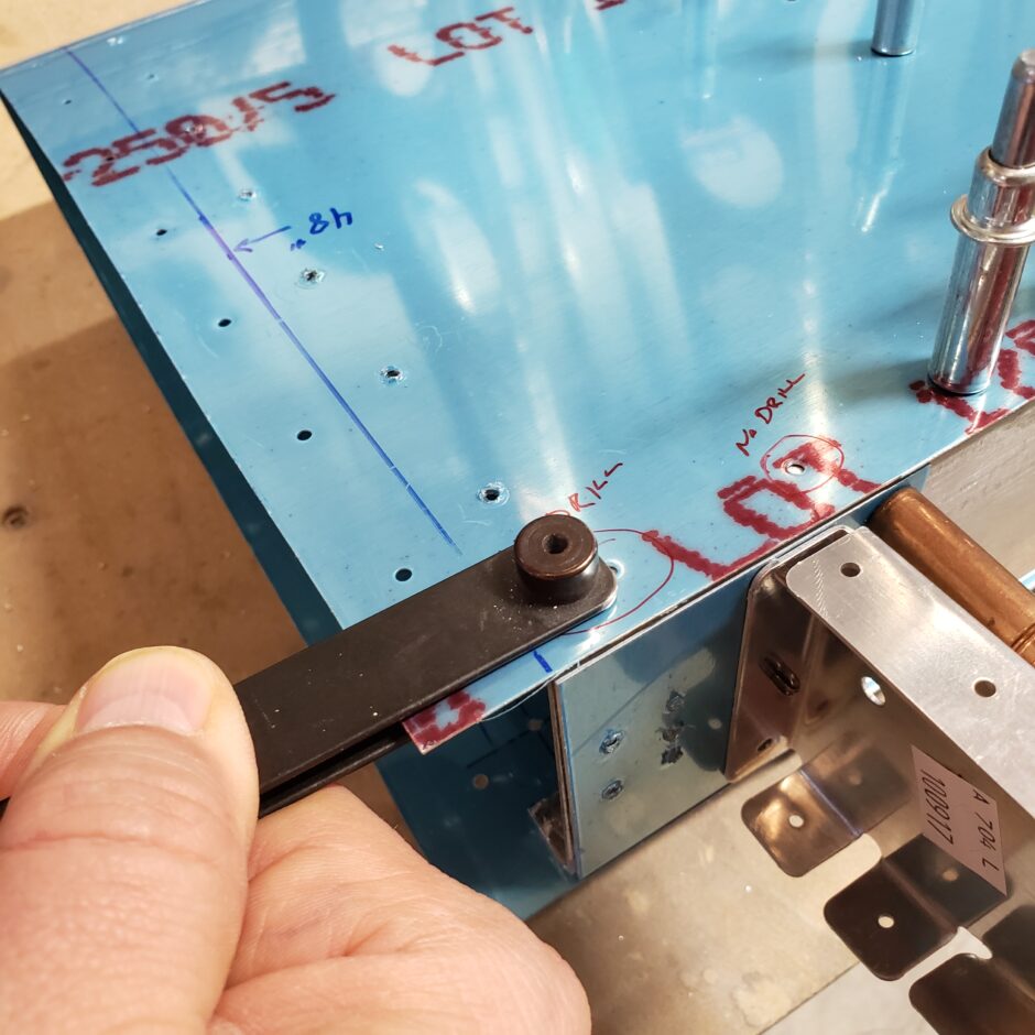
With the hole in the skin now match drilled to the spar and inboard trailing edge rib, you can now clearly see how there isn’t enough edge distance between this new hole and the pre-drilled hole in the skin for both to have a rivet in them.
For this reason, I chose to keep the predrilled hole in the skin undrilled to the spar. I’ll just leave the predrilled hole as is. I did the same for the top surface. These holes will be covered when the leading edge skin goes on, as it overlaps this entire area.
asd
Please comment. I love to hear from my readers. Thanks again for coming along for this ride, you make my work worthwhile.
Leave a Reply