I’m excited to get started on the F-404 bulkhead, but where to begin? For me to build the F-404 bulkhead for my F1 project, I’m starting out with the parts from my Van’s RV-4 wing kit. The bulkhead parts are all match-drilled at Van’s and pilot drilled from in their jigs.
Basically, the end goal here is that I need to increase the overall width of the F-404 bulkhead from roughly 27-inches to 31-inches, as the F1 fuselage is wider than the RV-4. If you were to build the bulkhead for the RV-4, the instructions in the RV-4 build manual would be sufficient. Using these same instructions for building the bulkhead for an F1…these same instructions are completely inadequate.
The main instructions for use here are a document put together by the folks at F1 Aircraft titled Main Spar Bulkhead, aka 404, aka #4, aka TR-F004. As stated in this 6 page instructional note, you WILL need a set of RV-4 plans and a set of HRII drawings. These instructions were pretty good…but some aspects just didn’t work, which I’ll explain later on.

The Big Picture
Before we get too deep into what to do, and how I went about building my F-404 bulkhead, I want to share a picture of what exactly it is that the end goal is in how to widen the bulkhead. In the picture below, you can see that there are 3 new pieces that need to be fabricated. These are essentially doublers that you are making to hold the extension (or widening) of the bulkhead together. The backside (against the jig board) needs to be flat as that is the side of the bulkhead that is bolted flush against the main wing spar.
I’ll try to describe what these 3 doubler plates are, working left to right. The first one (left-most) is the spar web plate extension. You can note that the bottom of this piece has a flange to match that of the spar web. This is the piece that the F-404A-R upright flange will sit on top of. The second, middle piece is a filler plate. With the first piece extending the spar web, the F-404A-R in the picture below, will now be sitting proud by the thickness of the upright flange. The second doubler is a filler piece that is used to provide sufficient width for the third piece (big doubler plate) to cover extend over the entire extension are. This third (big doubler plate) is what will tie all of the extension together.
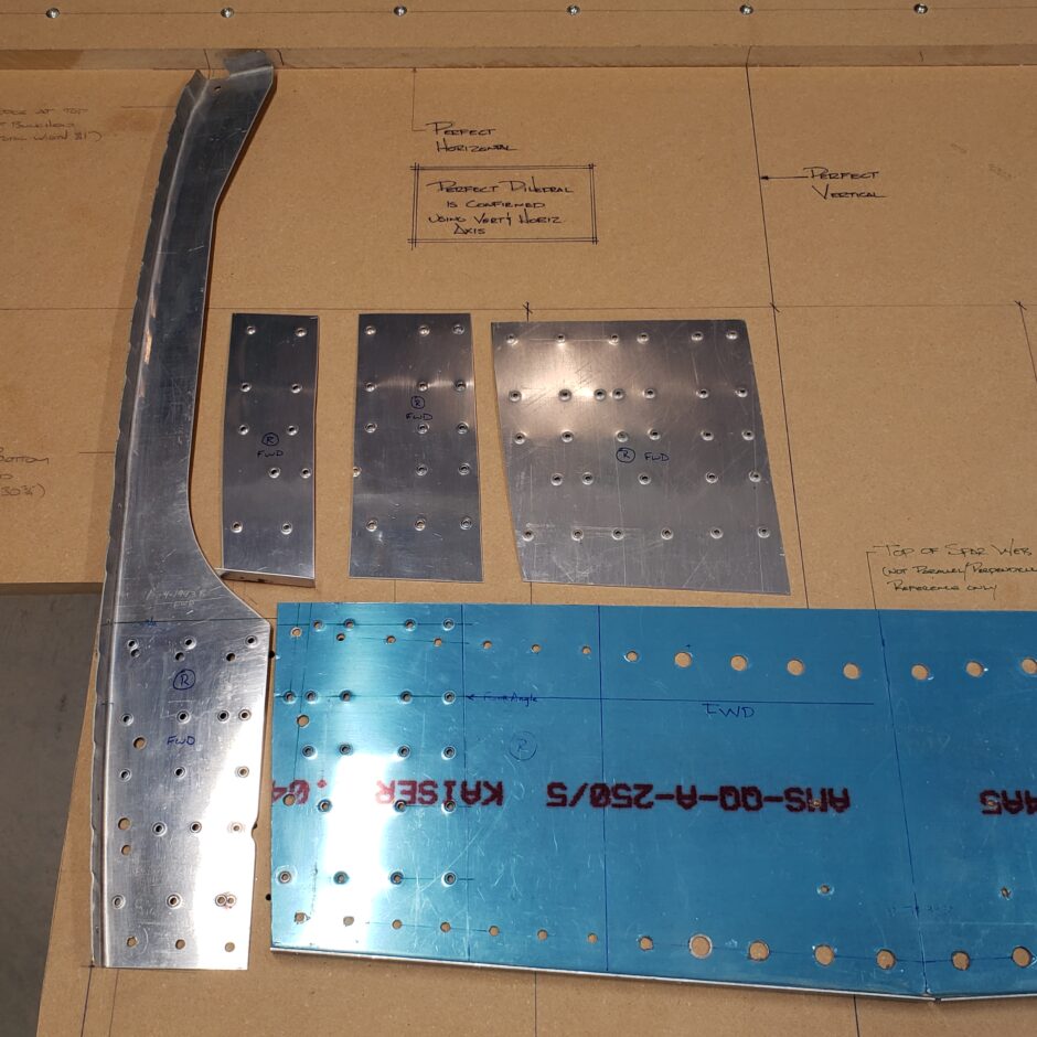
In the image below, you can see how all these new parts come together to widen the bulkhead. From my aircraft maintenance mindset, to myself I understand this as basically making a repair using a few doublers.
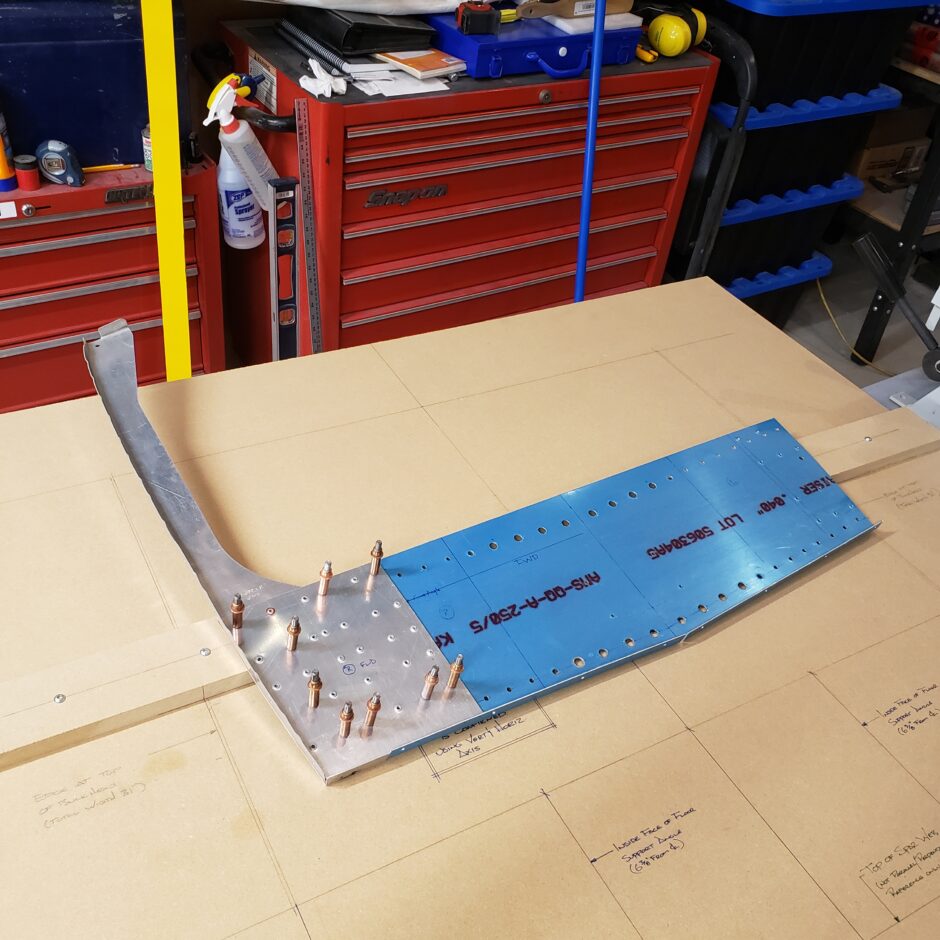
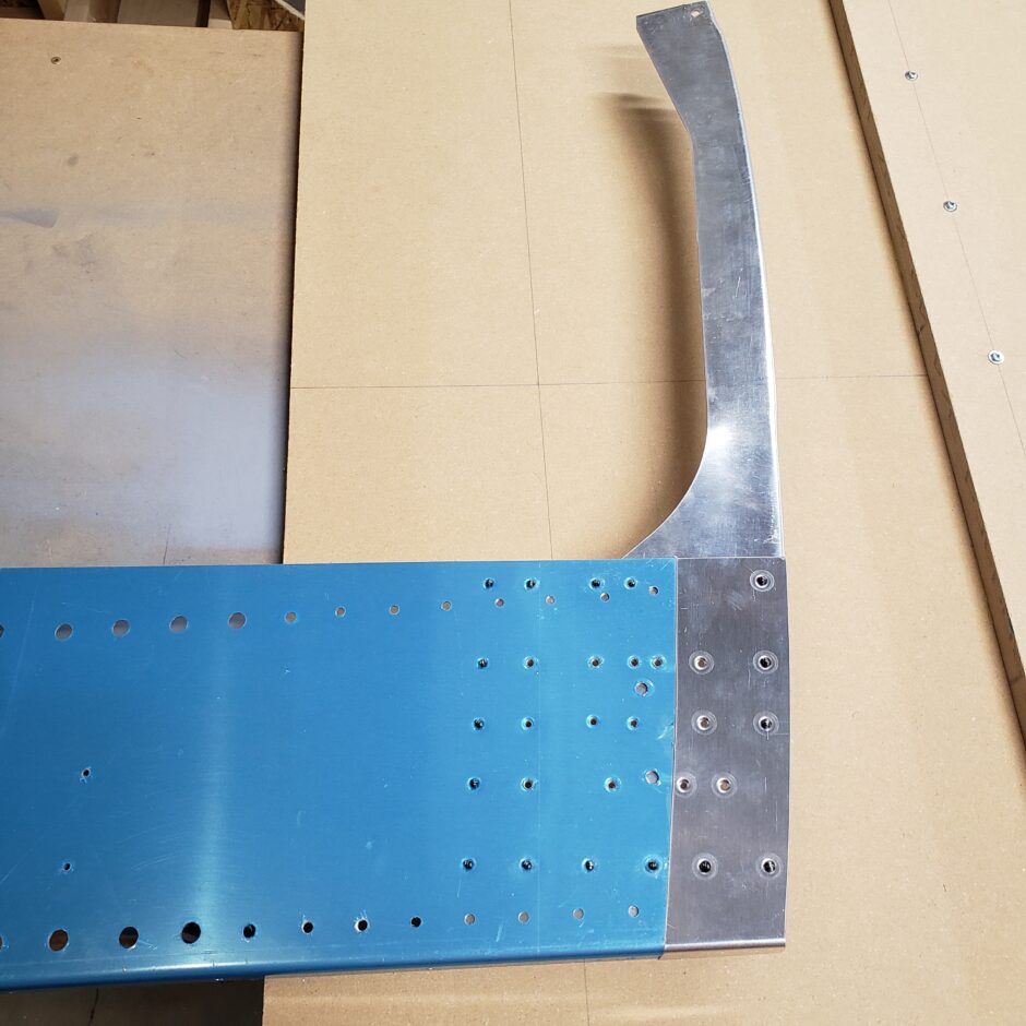
Below, here is what the backside of the bulkhead will look like with the spar web extension doubler in place. Again, you can now start to undertand why we there is such a big doubler plate on the forward side to tie all these doubler together.
Getting Started
The first step to widen the RV-4 F-404 bulkhead parts is to cut and bend a set of “filler” pieces. These are essentially extensions to the F-404C (forward bulkhead – spar web) and F-404D (rear spar web). The material here is 2024-T3 0.040″ thick.
In the picture below, I started to make a jig board using a scrap piece of plywood. The important part here is to layout a centerline and horizontal line to make sure the parts are square and symmetrical.
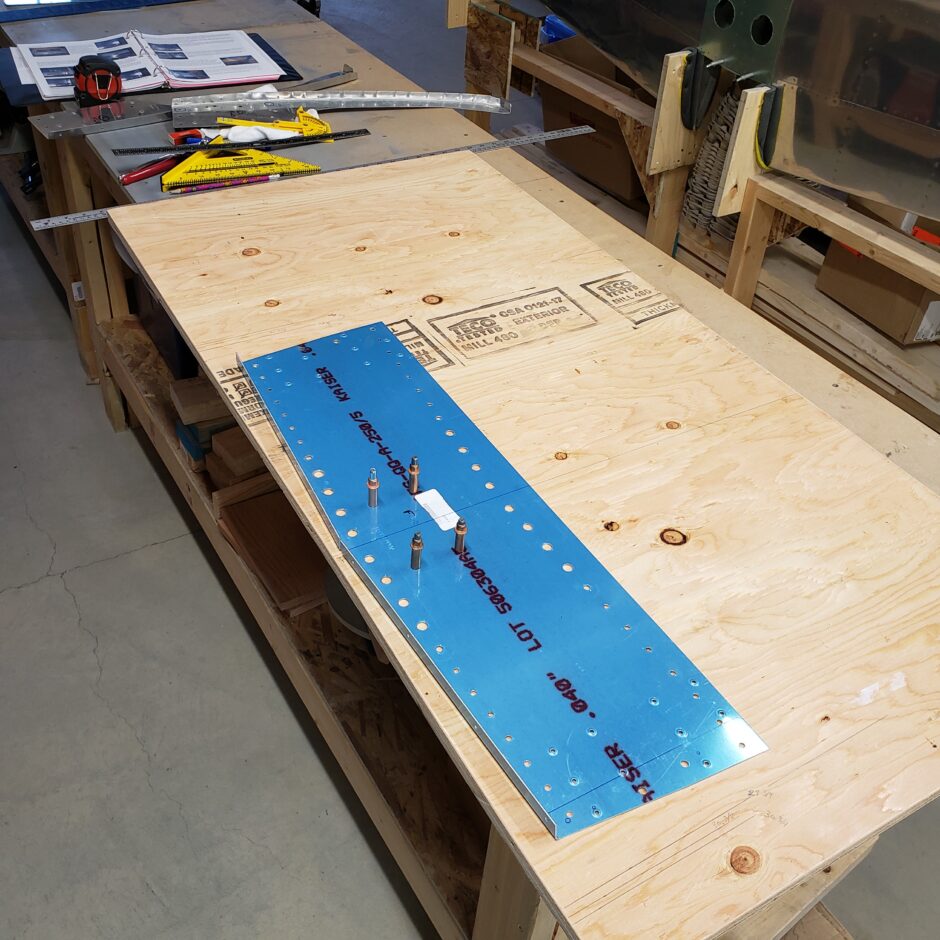
The image below shows how I started the filler pieces. I made sure the part was generously wide to allow for trimming after. You can also note that the lower flange to be bent is also generous in its dimensions.
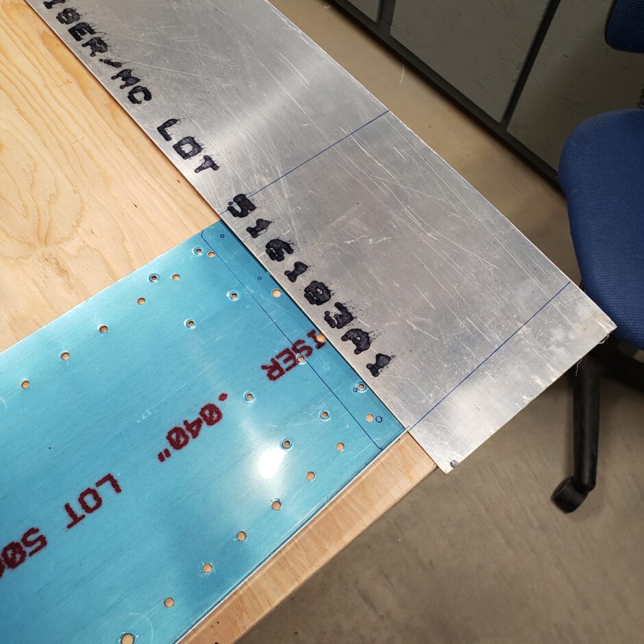
Below the filler pieces are cut and the flanges bent to give me a starting point.

I began to put the upright bulkhead formers on the spar web plate to start trying to get these parts located.
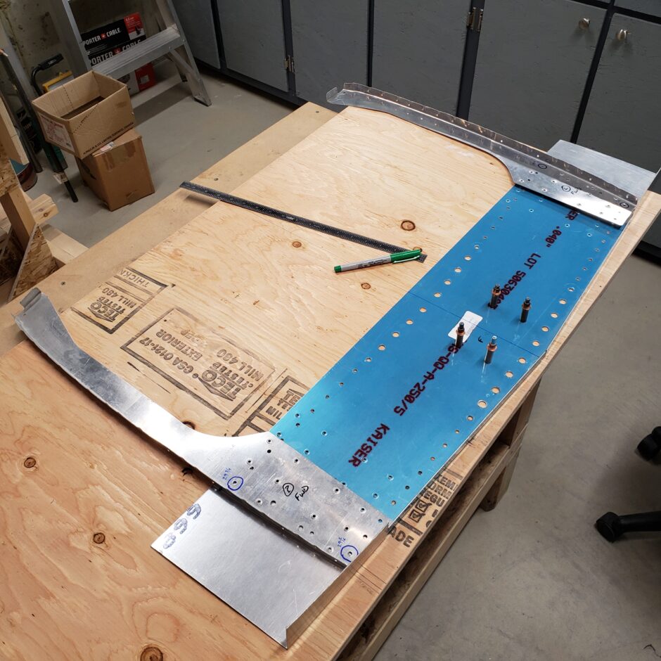
As all these parts are predrilled in the RV-4 bulkhead jig at Van’s, just note that very few of the original holes are going to line up. In the pictures that follow, you can start to get a sense of the good times that lay ahead.
F-404 Bulkhead Plans Clarification
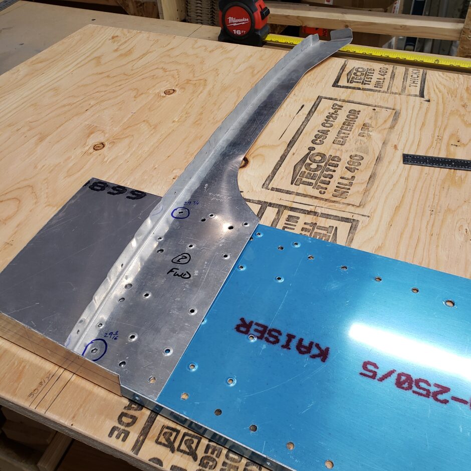
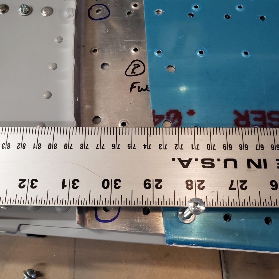
An important note that I want to share here is to discuss one of the notes given in the instructions provided by F1 Aircraft which state in part…“The holes circled are important for jigging up the assembly when making the filler pieces. The top holes are set 29 3/4″ apart and the bottom holes are 29 11/16″ apart.”
As a good builder, I identified these pre-punched holes in my parts (as shown in the picture below). That’s where I first ran into my troubles. Ultimately I could either get the outer dimension to work (ignoring the pre-punched holes) or I could set the PP holes to the correct dimensions and not acquire the correct outer dimensions.
Spoiler Alert…after building the F-404 bulkhead, I just want to add regardless of what the F1 Aircraft instructions stated about the pre-punched holes. I did not use them in the end. I can only assume that they are related to holes made in the parts formed by F1 Aircraft and are not applicable to Van’s RV-4 parts. Throughout the build of my F-404 bulkhead, these holes did not ever align with any of the pre-punched holes in the main wing spars. My advice to future builders, if these PP holes are giving you grief, just ignore that part of the instructions and move on as I did. Make your own measurements to ensure square and symmetry in your build.
In trying to heed the instructions of the importance of the pre-punched holes, I ended up putting the forward bulkhead assembly right on the spars to help me understand why the instructions go on about these holes.
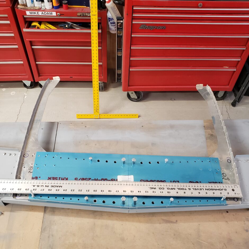
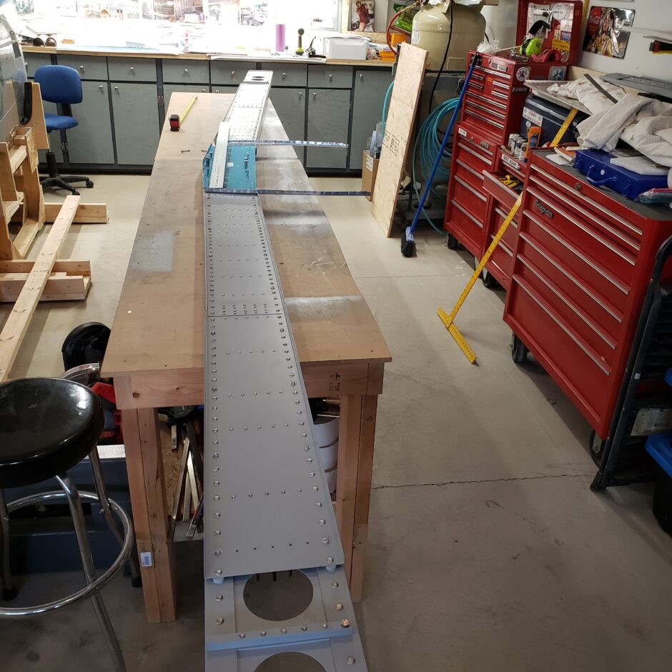
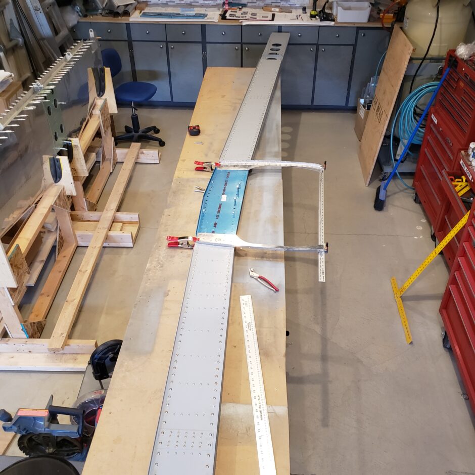
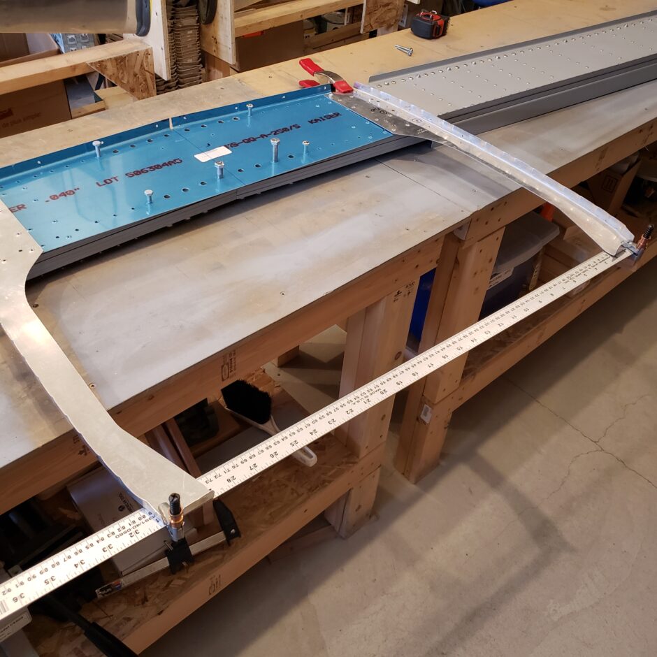
Well, needless to say, I cannot figure out the dimensions given and am going to call it a day. Time to go and rethink my strategy for building the F-404 bulkhead. Please comment. I love to hear from my readers. Thanks again for coming along for this ride, you make my work worthwhile.
Leave a Reply