Good day! Today I’m going to continue with the fixed leading edge skin rivet layout. Now that I fixed my clearance issues on the wing jig, I can now get the skins to lay flat against the ribs, with the proper 1/2-inch of overhang on the outboard edges.
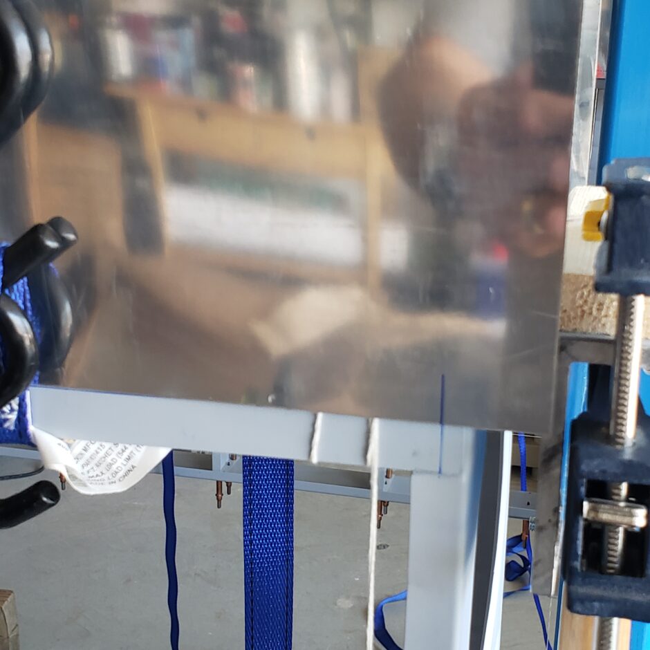
Previously I have marked the centerline of the rib flanges. Following that I extended those centerlines down onto the main wing spar flange, so that they extend beyond the leading edge skin when the skin in strapped down. You can see this in the picture below. Apologies for the blurry image, but you get the idea.
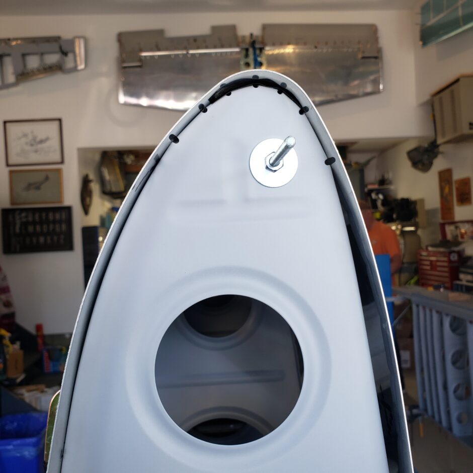
Again, here’s another picture of the leading edge bend, and how well Harmon Rocket is able to form these parts. Its really impressive.
To begin getting these wing skins ready to do the rivet layout, I started by using ratchet straps to hold the skins in place. This job is much easier with 2 people, but you can definitely do it on your own. Just go slow, as it’s a bit of a juggling process trying to get the straps on.
Just try and get the straps on loose, then start evenly working them tighter and tighter. At first you’ll be working against the spring tension of the skin, until it’s seated against the ribs. Then you can start getting the straps tighter, while working the skin in place.
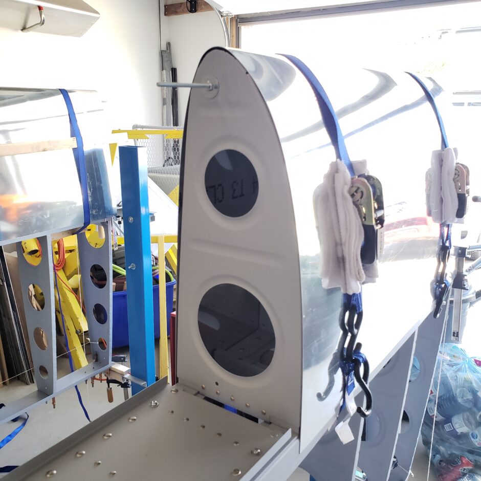
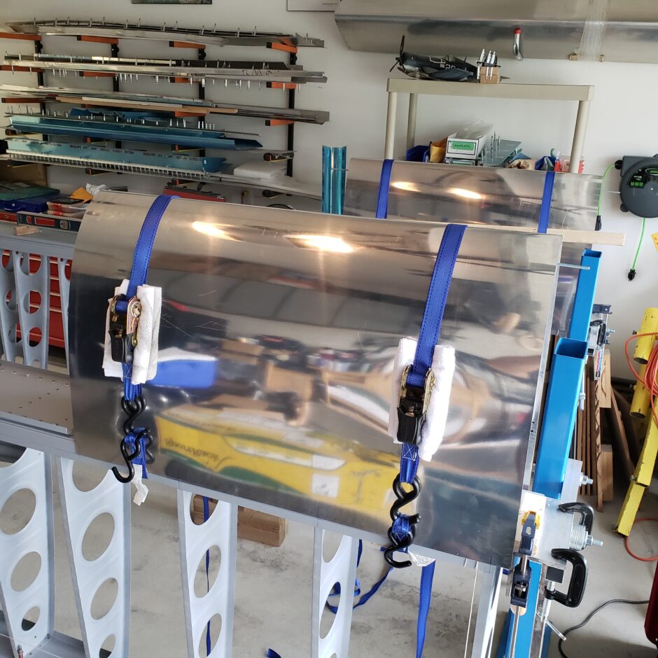
When getting the skin in place, basically you want the skin even with the inboard ribs (facing the fuel tank), you want at least 1/2-inch of overhang on the outboard edge, and along the spar flange, you want both upper and lower surfaces of the skin to stretch out to the skin butt-joint line that we laid out previously. This is where you need to ratchet down the straps, because there is NO excess material in these skins. They are perfectly cut to size…well maybe 1/32-inch of excess, but it’s not a lot if any.
Also make sure that you have the leading edge of the skin sitting tightly against the leading edge of the ribs. I used a rubber mallet to help get things where they needed to be. In the picture below, you can also see that I used some shop rags to protect the skin from the straps rubbing and marking the skins.
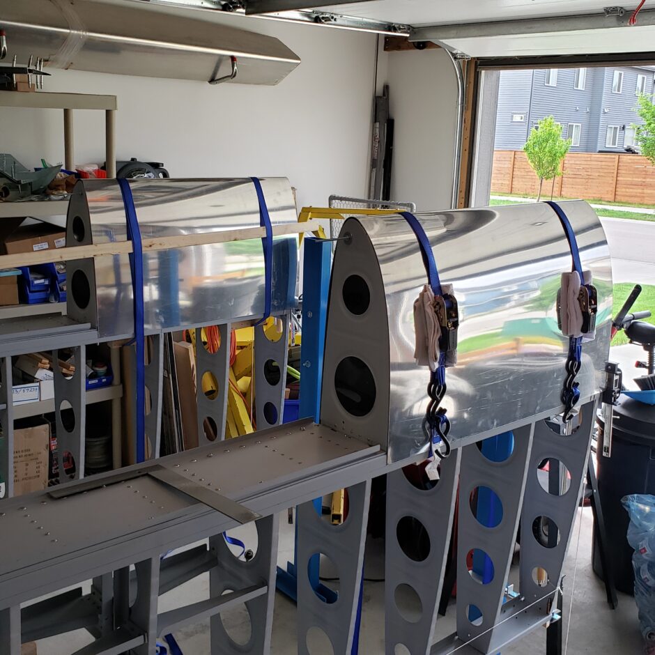
In the picture below, you can see that I’m getting the skin close to the butt-joint line on the spar flange. This can be one of 2 things. First, you need to ratchet the straps a bit tighter OR…check on the other side (upper or lower surface) and see that the skin is evenly positioned. You might find that the skin on the opposite surface might be over the butt-joint line by the same amount. If this is the case, you can try and persuade it with the mallet on the edge of the skin, or just loosen the straps a bit, nudge the skin in the desired direction and start to tighten the straps again. Take the time necessary to get it right!
Once you’re happy with how the skin in positioned, then you can transfer those rib flange centerlines (that were extended out on the spar flange) up onto the leading edge skin. This will be the starting point for your rib rivet layout lines.

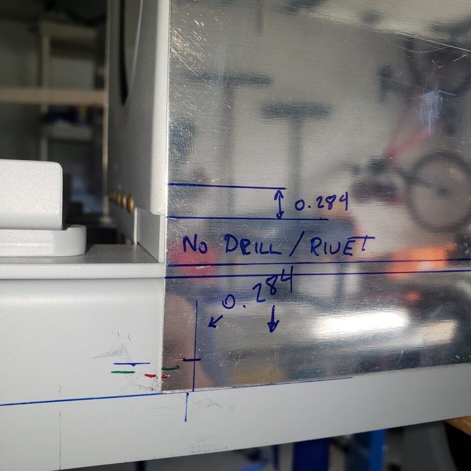
In the image below, I identified some really important items on the skin to help prevent me from drilling into something I don’t want to. The first thing to note here is the 0.284 dimension I have shown. This is the dimension I have for where the rib flange centerline is in relation to the inboard edge of the skin.
I also used the 0.284 inch dimension as my edge distance for the lower edge (butt-joint edge with the wing skin – blue sharpie lines – not the red and green marks) and also for the edge distance up from the cutout edge of the wing rib. The plans call for 0.250 inch edge distance for the rivet line along the main spar flange. As there is plenty of room here for the rivets I opted to go with a bit more edge distance and kept it at 0.284. This way, should I have to trim the skin, I still have some material to work with and can also be close to the plans 0.250 inch edge distance.
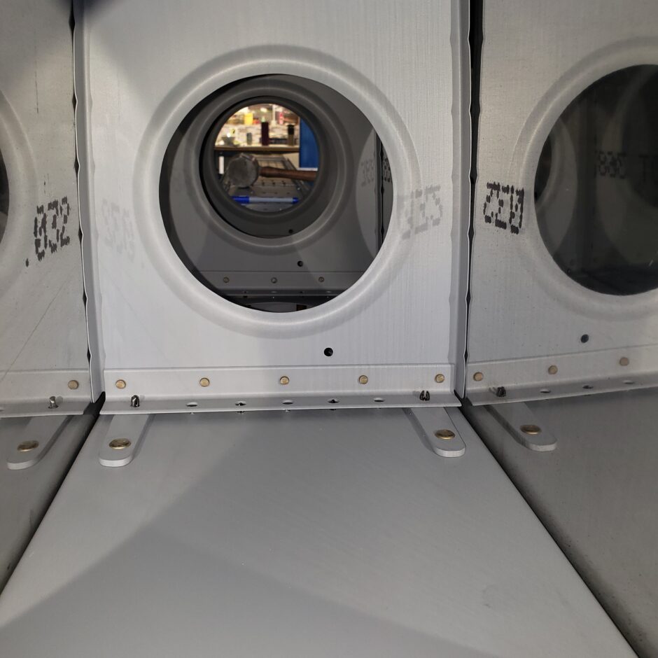
Here’s a shot of the inside of the leading edge. You can see how the rib flange ends just slightly above the main spar. This gap is to account for the spar stiffener beam. Again, make sure you check what is hidden under the skin compared to what you have marked for the layout on the outside surface. Measure, measure, measure! Lots of visualization too.
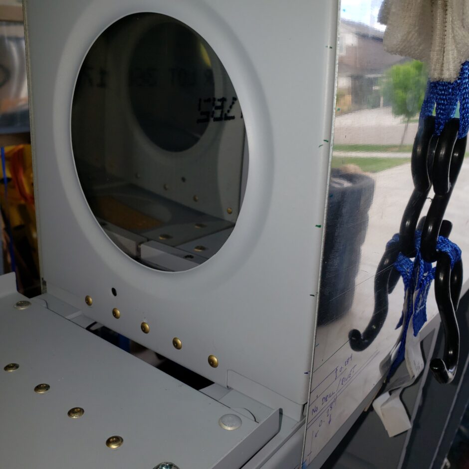
In the picture below, you can see a better picture of the inboard most rib and the cutout that you need to account for in measuring your edge distance up on the rib flange.
Moving up to the tip of the leading edge, another thing to mark or identify, is where the rib flange tab cutouts and flutes are located, as you don’t want to locate any rivets in those areas. While we are looking at this picture below, I also want to explain that the blue dash, between the green lines is what I used when I started to layout and measure out the rivet spacing. When I measured out the rivet spacing I started at this point close to the tip of the leading edge and then worked my way back. There are a few pictures further on that show this in more detail. I used this blue dash dimension for the starting point on all the ribs straight across. I started here, as it’s easy to see the relief cuts and flutes on the edge of the inboard rib. This makes it easy to have a good starting point.
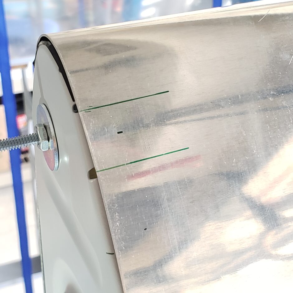
Previously I extended the rib flange centerline down onto the spar flange. Once the skin is in place and you’re happy with the positioning of it, then you transfer that line again, back onto the wing skin. Using that starting point, I then used a square to ensure I drew a straight line where each rivet line would be drilled in the skin.
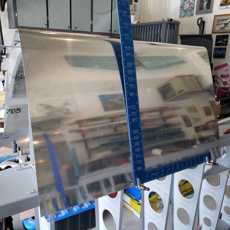
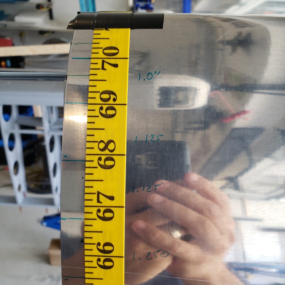
With the vertical rib rivet lines drawn on the skin, it was then time to measure out the rivet spacing on each rib. In the picture below, you can see I did this by using a sewing measuring tape. This worked out extremely well. I taped it to the tip of the leading edge and then used a cleco clamp to hold it taut along the rivet line. The placement of the tape, in so much as what set of numbers you’re working with doesn’t really matter, as you’re only using it to get accurate rivet spacing, not necessarily using it to measure distance.

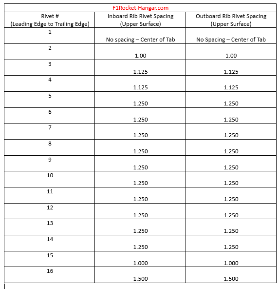
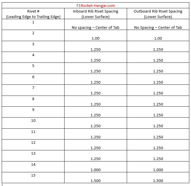
In the picture below, again, you can see that blue dash that I used to start measuring the rivet spacing, working my way aft along the line. As all the fixed leading edge ribs are the same, it’s easy to do the layout once you get the first rib figured out. At the end of this post, I’ll add a table with the measurements I used for my rib spacing. The RV-4 drawings call for 1.250-inch spacing. As you can see below, the spacing between the first and second rivet on mine was 1.00-inch. If I used 1.250 spacing here, the rivet wouldn’t sit in the middle of either flange which would give me some edge distance issues, or the second rivet would be really close or interfering with the flute. Additionally, you can see some of the other rivets needed to be spaced at 1.125-inch for the same reasons. So yes, you need to follow the plans, but don’t blindly trust them.
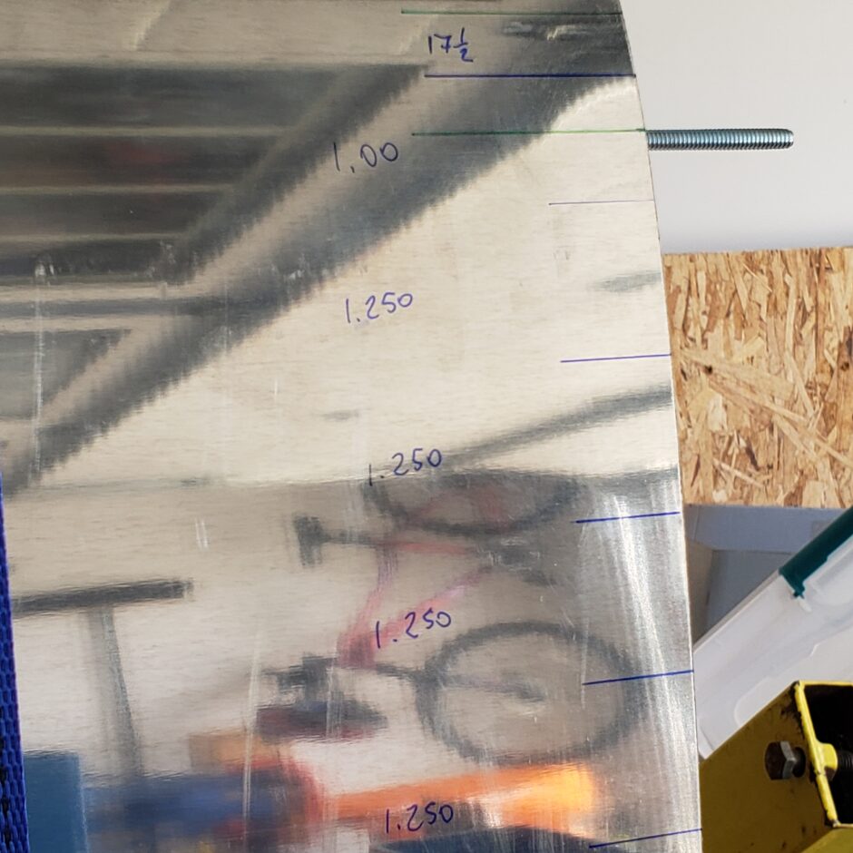
Here is a closer look at how I marked the layout for the rivet lines. This particular image is on the upper surface of the outboard (tip) rib. The blue lines are the rivet location, and the spacing is identified between these lines. This picture is also obviously before I transcribed the vertical line. The 17 1/2-inch dimension at the top is the overall dimension of that rivet line from the first rivet at the tip, to the last rivet of the rib (not extending onto the spar flange). I used this dimension to set both the first and last rivet in the line and to give me the same layout starting point on each rib. (See the table below).
Here is another picture of the lower surface of the leading edge with the vertical rib lines marked.

On this fixed leading edge, as all the ribs are the same, I only measured out the inboard and outboard ribs for rivet spacing. Then, as shown below, I used a straight edge that I could clamp on either side at the appropriate rivet line, and then for the middle 2 ribs, it was easy to transcribe the proper rivet location marks.
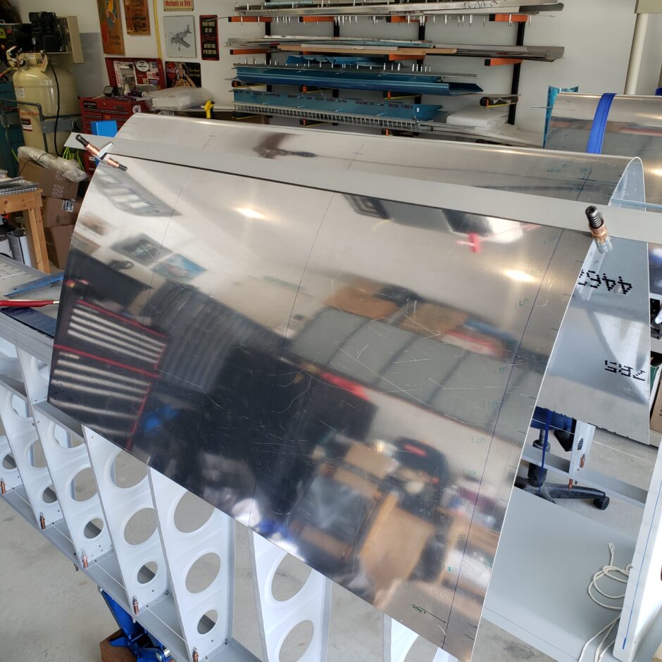
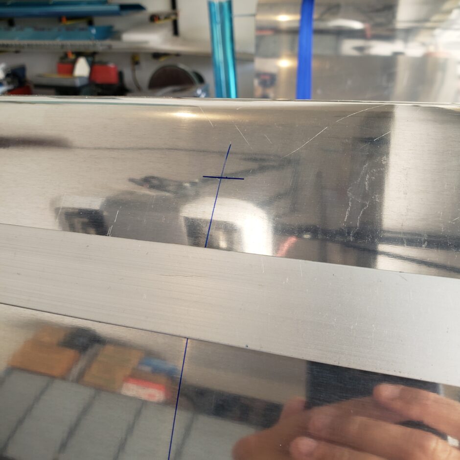
Here is the leading edge with all the rivet markings on the upper surface.
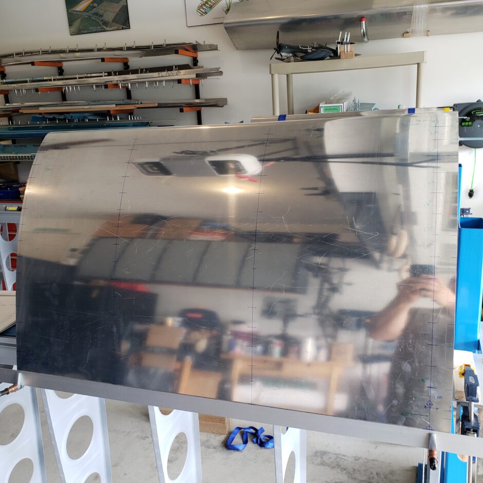
This is just a picture showing the spacing of some of the rivet locations.
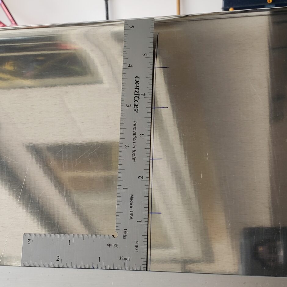
In the table below, I have identified the fixed leading edge rivet spacing that I used.
That’s all for today folks! Please comment if you find this post helpful. I love to hear from my readers. Thanks again for coming along for this ride, you make my work worthwhile.
Leave a Reply