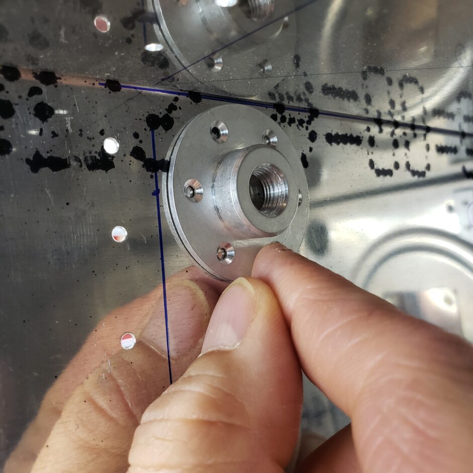
Good day, today I’m working on getting the fuel drain fitting and the fuel tank filler cap fitted to the tank skin. I’m starting out with the easier of the two, the fuel drain fitting. I began with getting it located on the inside of the tank. In the picture below, I have the rear tank baffle in place, and I have the root rib out. I also previously drew a line along the inside surface of the root rib for this positioning. The goal here is to get the drain as far into the corner (the lowest point of the fuel tank) as possible.
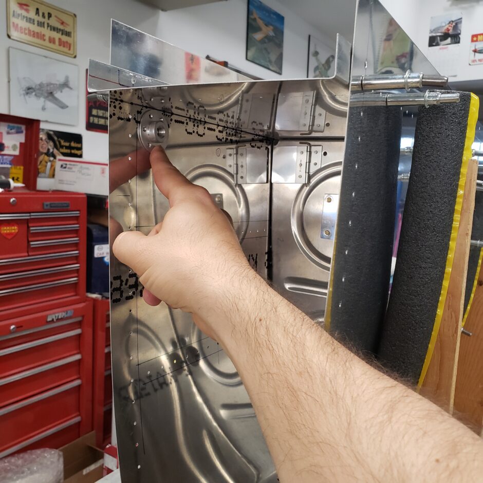
Here’s a shot of the same as above, just further out.
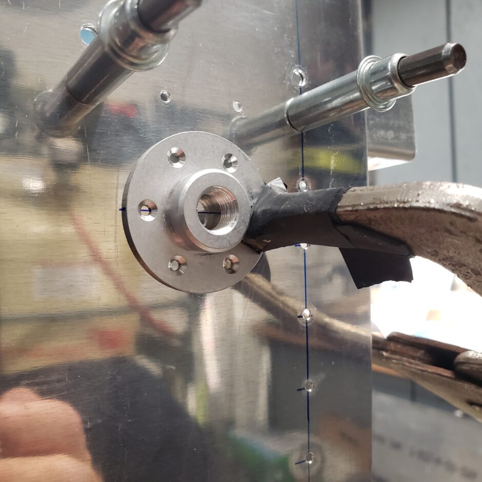
Next I made 2 marks in the horizontal holes of the drain fitting to get a centerline of where the fitting needed to be located. I then joined those dots into a line.
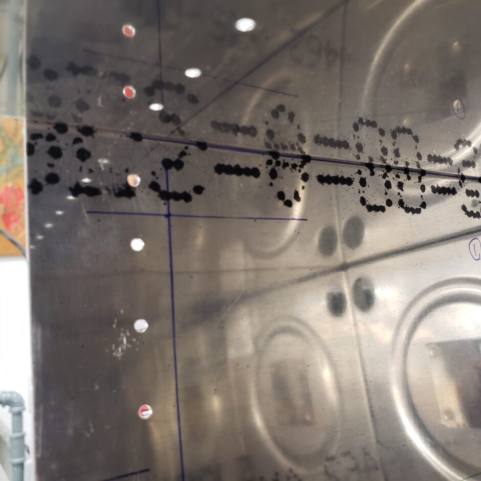
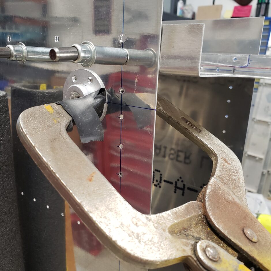
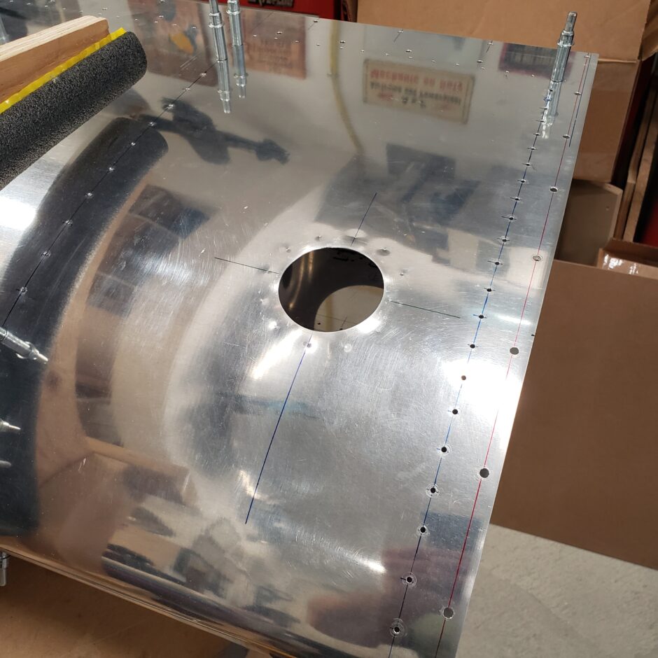
Then I transferred the line from the inside of the skin to the outside. I also measured the fitting location on the inside of the skin (distance from skin edge to inboard edge of fitting) and transferred that to the outside as well. Once I was satisfied with placement of the fitting, I clamped it in place.
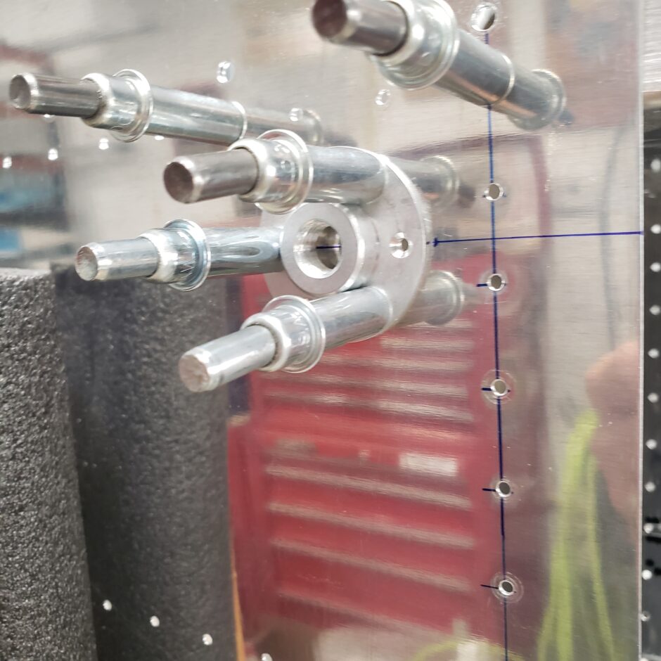
In the picture below, you can see how I picked up on the centerline.
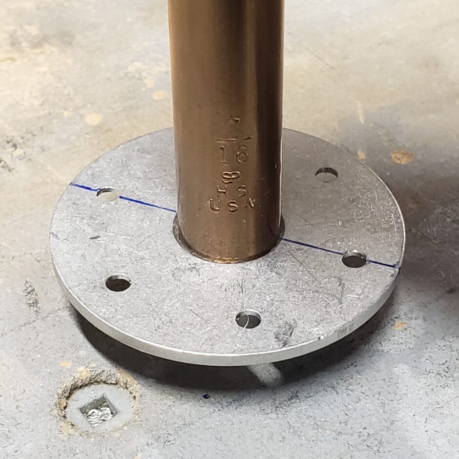
Once the location of the fitting was determined, it was easy to get it drilled.
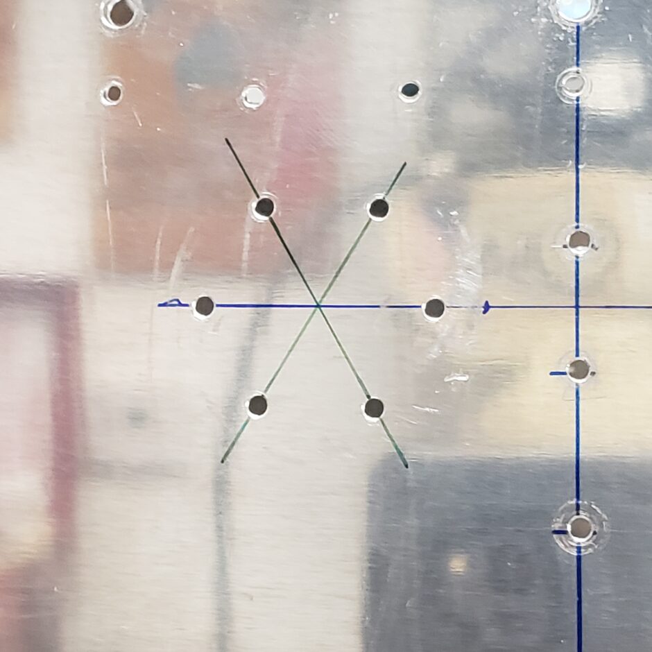
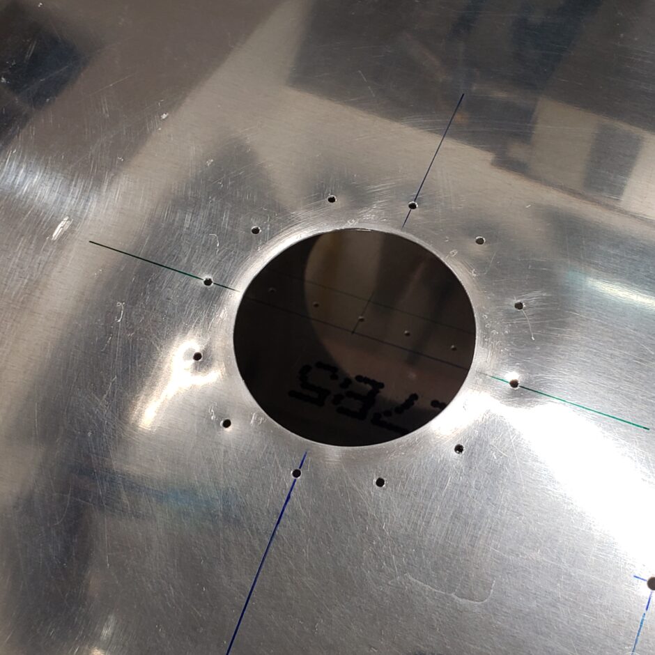
I wasn’t sure what the best way to identify the middle (drain hole) location so I kept it simple and just connected the dots through the middle and that’s where I ended up drilling.
The plans again were silent on just how big the drain hole needed to be, so I used my drill bit set to determine what a suitable size hole to be made in the skin. I can’t remember what I used but it looks like it was 7/16 in the picture.
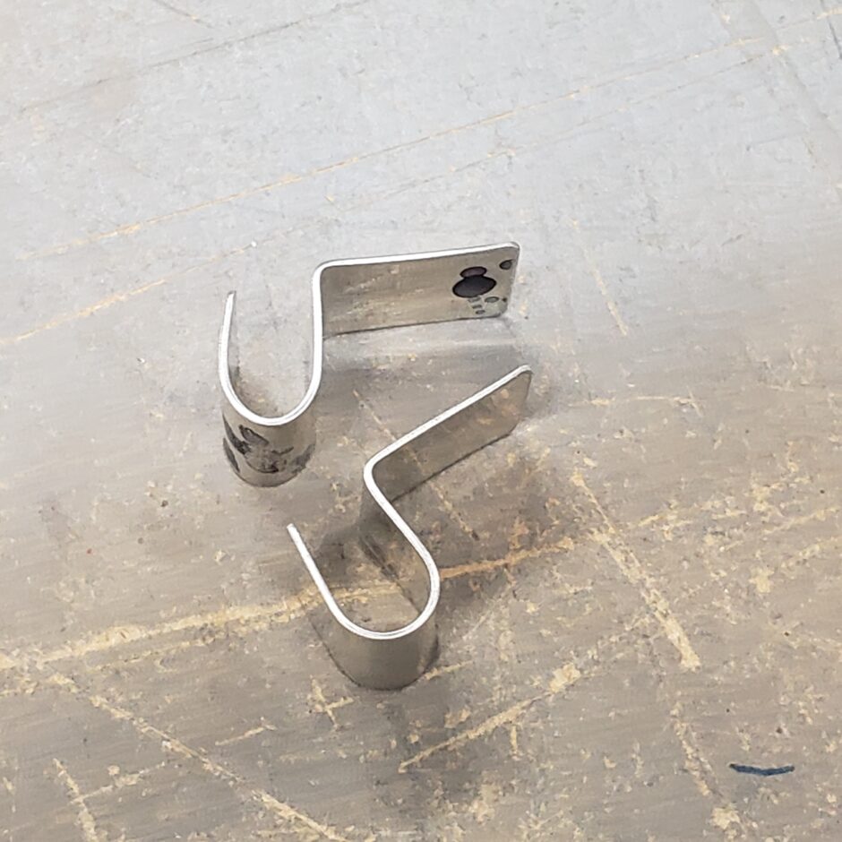
With the fuel drain flange fitted, I finished up the vent line brackets that are riveted to the bottom side of the fuel filler cap assembly.
Fuel Tank Filler Cap
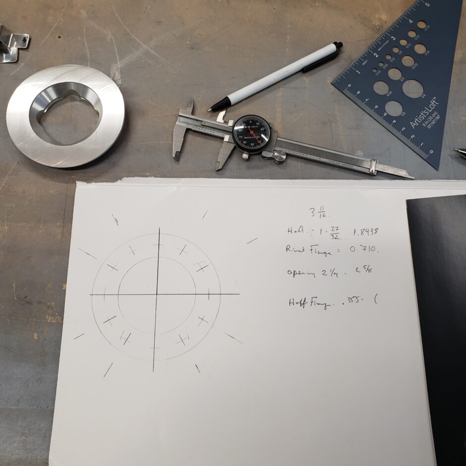
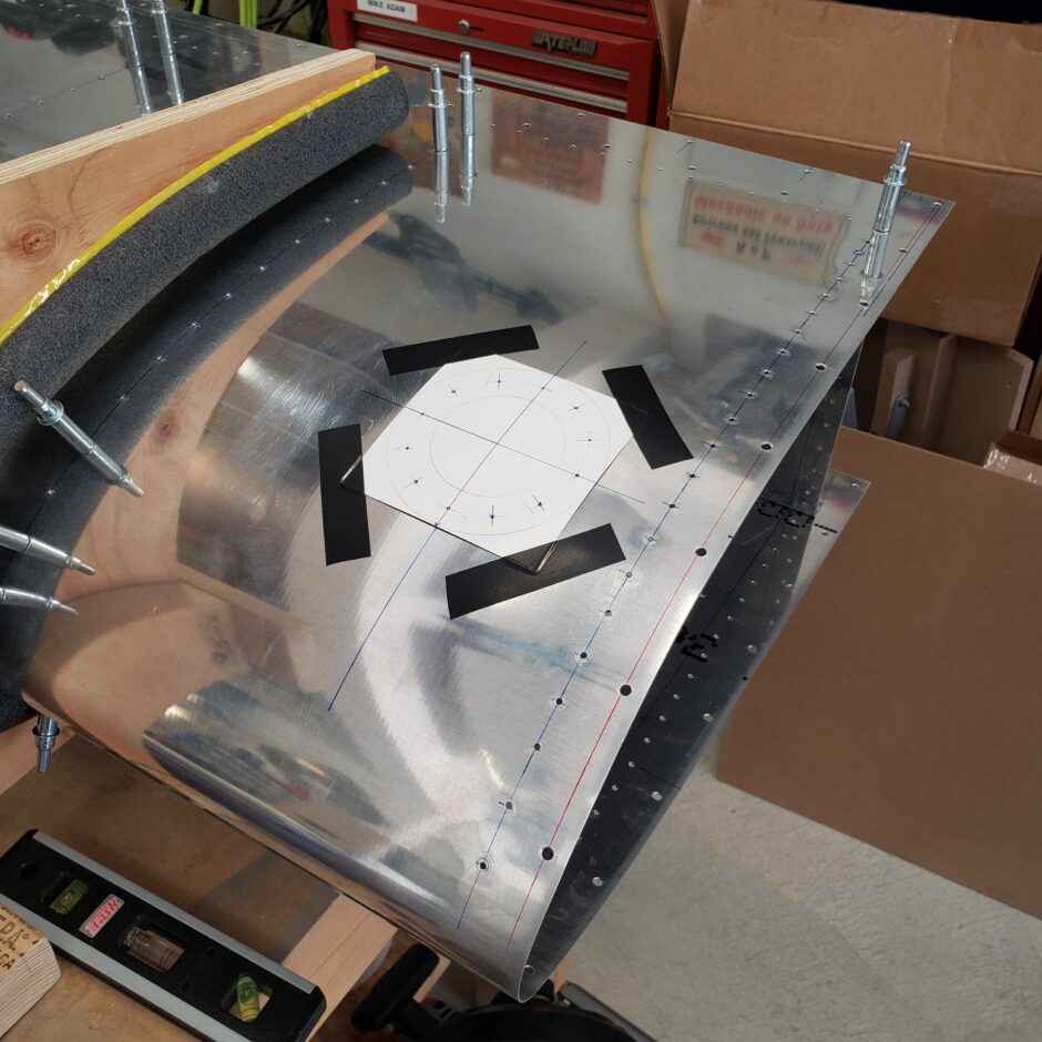
Next I moved on to the fuel tank filler cap installation. As you can see below, I did a bit of measuring to make sure that I got the rivet layout exact. I started by measuring the size of the flange, then figuring out the middle. As it was too difficult for me to try and do this on the flange itself, I drew it out on some thick cardstock.
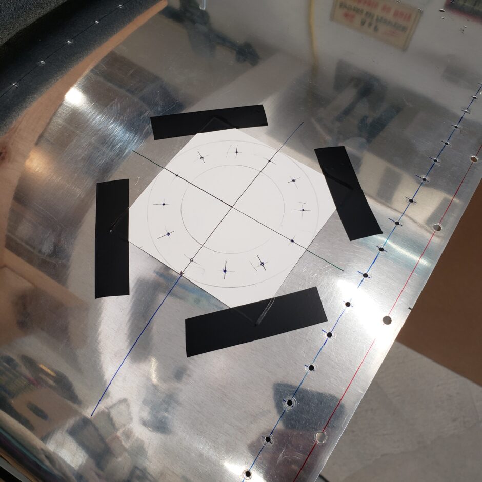
Once the template was made, I cut it out, center punched the holes and then clamped it to the flange to mark the holes with a Sharpie.
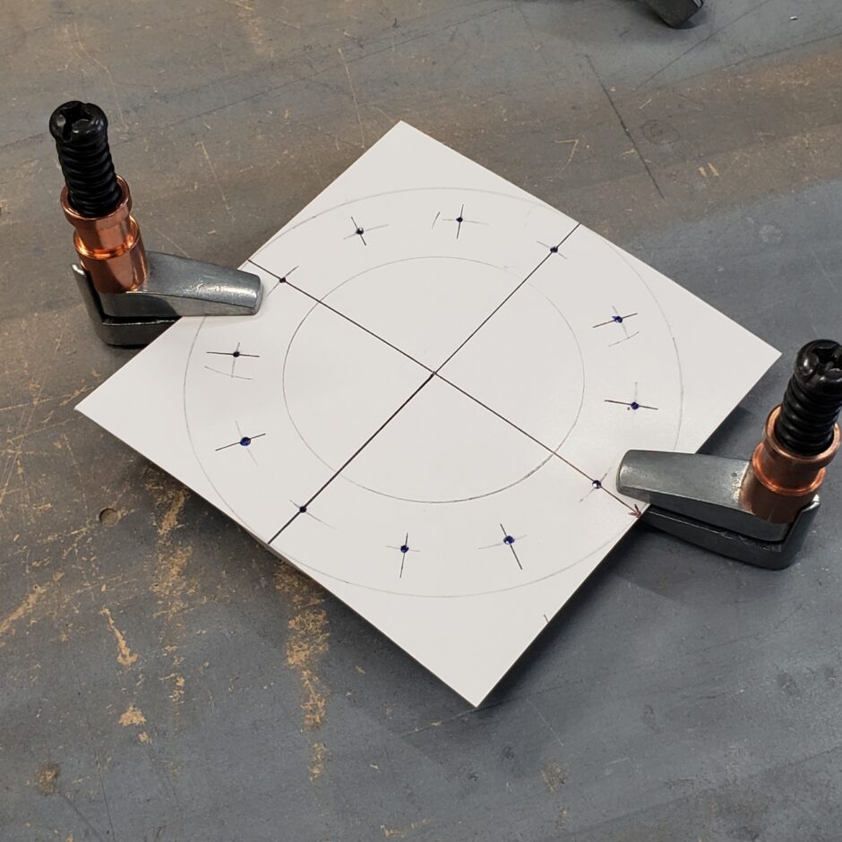
Next I measured where the center of the filler cap opening needed to be, extended the lines and overlaid the template to align with the locator lines. Then taped the template in place and center punched all the fastener holes and the center hole.
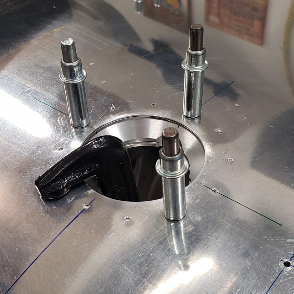
To cut the filler hole in the tank skin I used a 2 1/4-inch hole saw. I made a guide out of some hardwood which I clamped to the skin, and made a 1/4-inch hole to center the hole saw. This technique worked out really well.
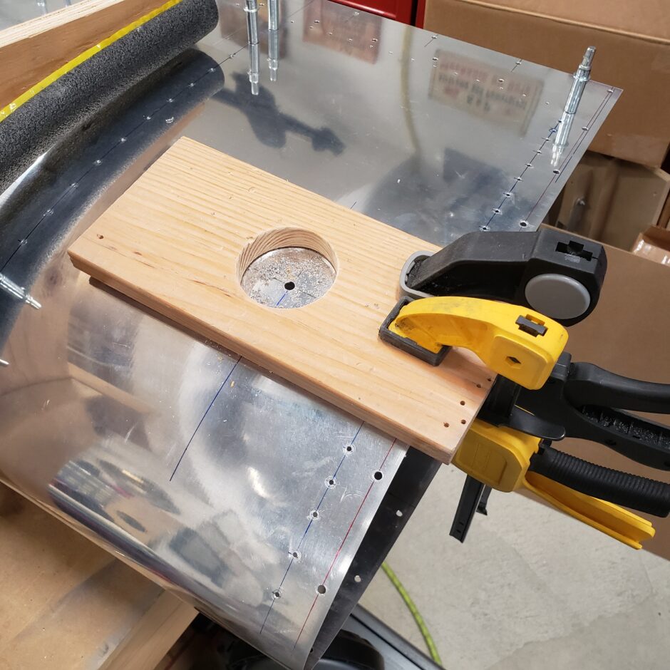
The hole saw and guide did a good job with very little edge dressing to do. I mostly used a chip chaser around the hole a few times before hitting it with a scotchbrite pad.
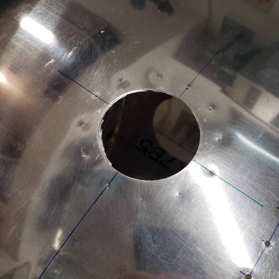
I probably don’t have to tell you but take your time here. You’ve got one shot at this without screwing it up so don’t rush it.
With the hole cut and the rivet holes drilled, I clamped the filler cap assembly in place and then started to drill the rivet holes. For this I alternated sides to help keep clamping pressure and cleco pressure even while I drilled to keep the flange flat.
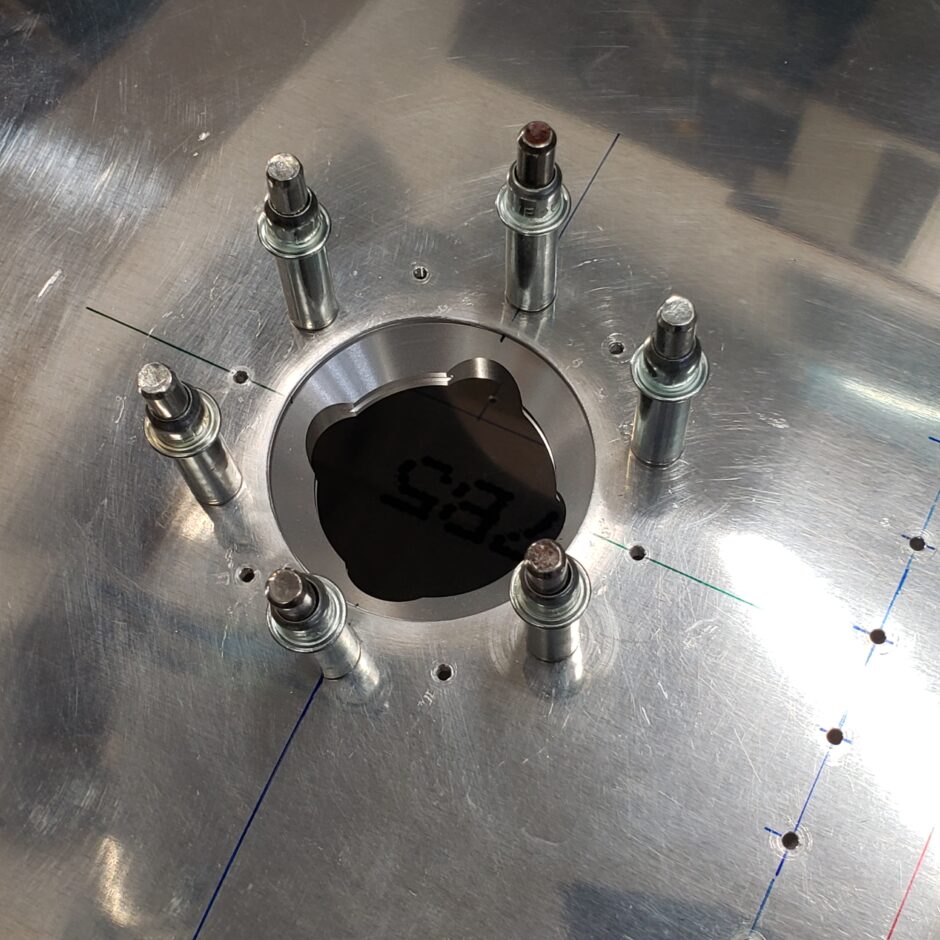
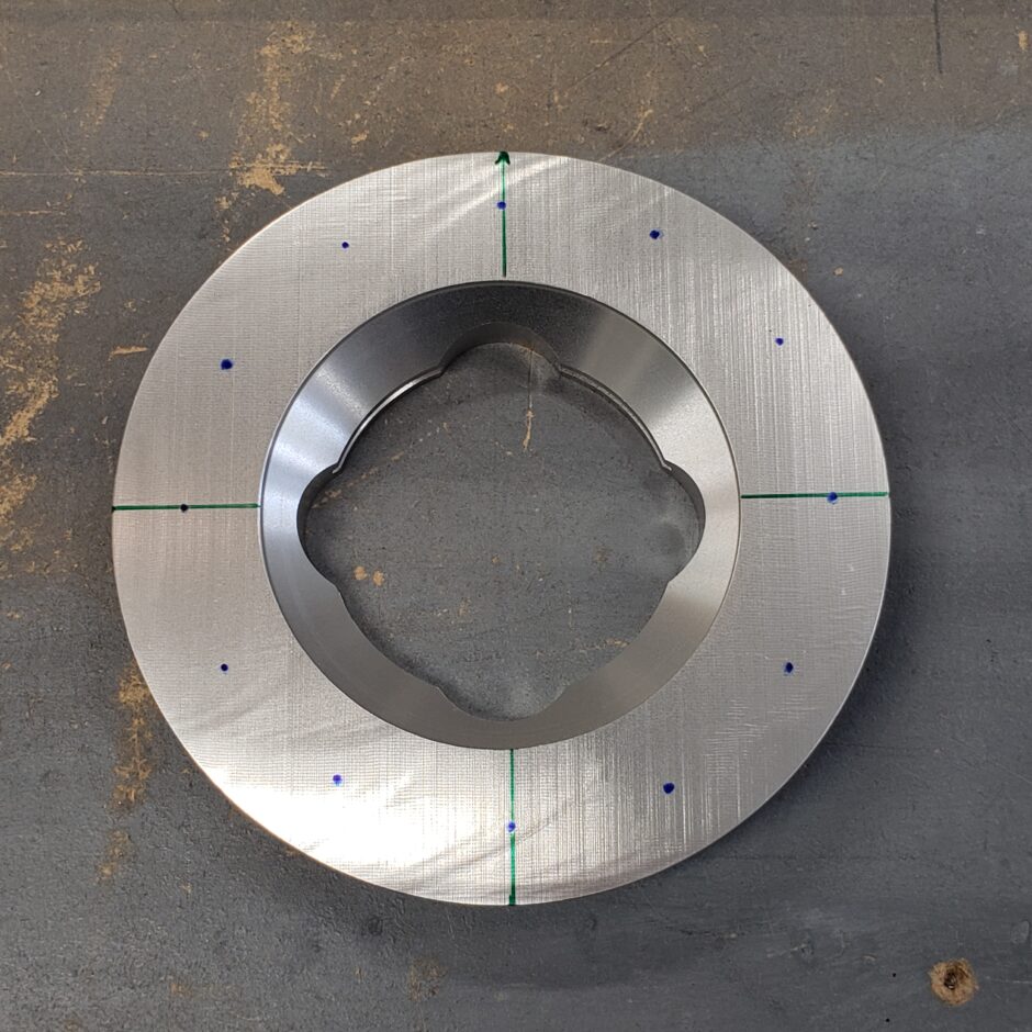
All in all, I’m really happy with how this turned out. The cap fits beautifully in the skin. I’m also really happy I splurged for the upgraded filler caps. These are downright beautiful.
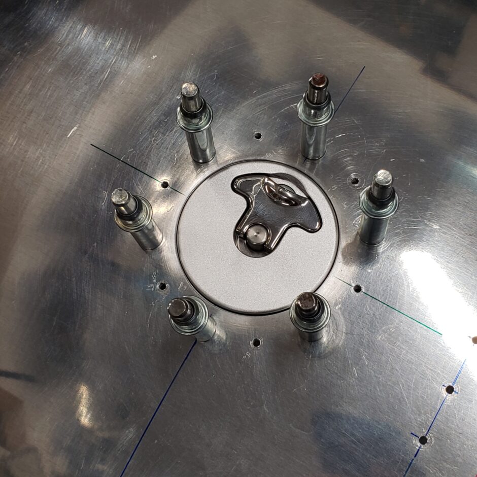
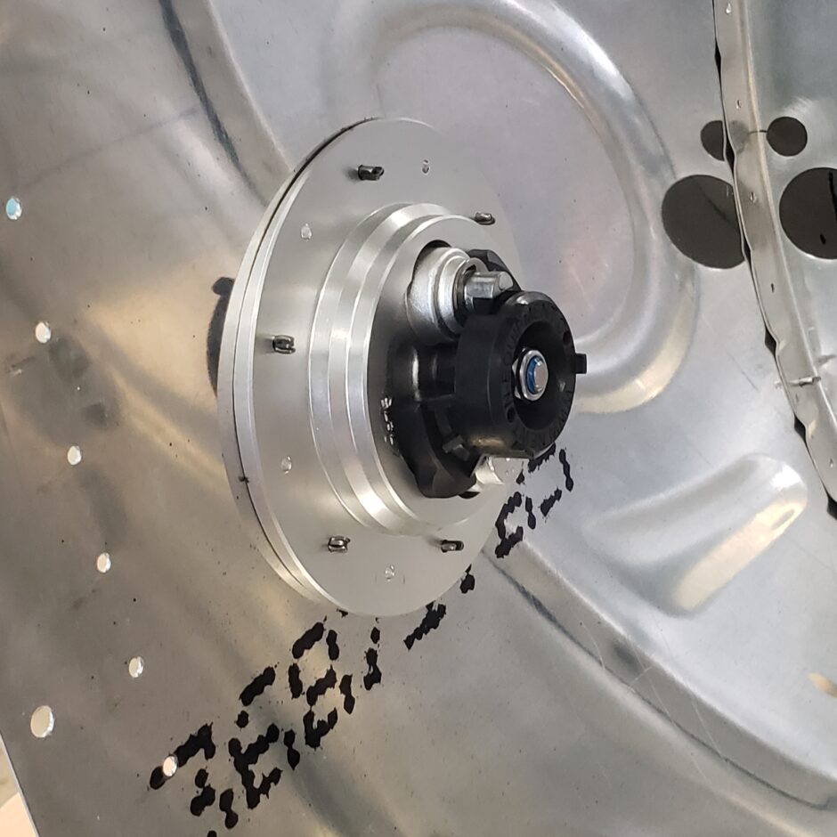
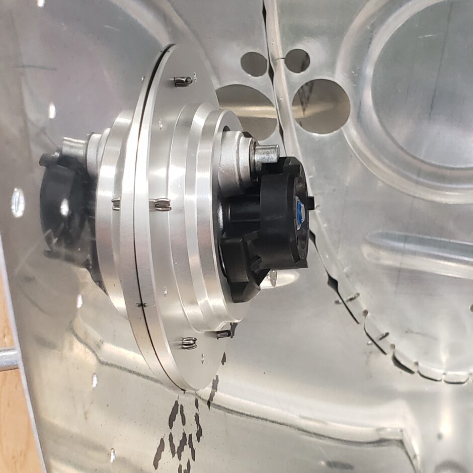
Finally, here are some shots of the inside and how well the contoured flange fits against the curvature of the skin.
That’s all for today folks! Please comment. I love to hear from my readers. Thanks again for coming along for this ride, you make my work worthwhile.
Leave a Reply