Now that the fixed leading edges are drilled and clecoed in place, it’s now time to begin working on the rest of the wing leading edge…the fuel tank!
To begin on the fuel tanks, the first place to start is by fabricating some spacer blocks that you can use to acquire the proper spacing of the fuel tank rear bulkhead and the forward spar flange. As the F1 Rocket, Harmon Rocket II and RV-4 all don’t have Z-Brackets like many of the later Van’s kits do, spacing on the front side of the spar needs to be determined by use of these block. I made mine to sit within the main spar rivets. Roughly 5 1/2-inches in length.

I used oak to fabricate these spacer blocks with because oak is always nice and stable to work with. I didn’t get a picture of it, but I did run the oak board through a thickness plainer to help me get the proper dimensions.
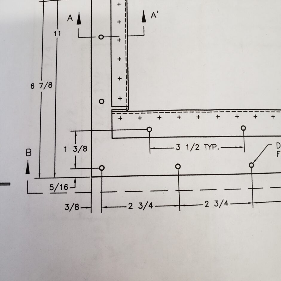
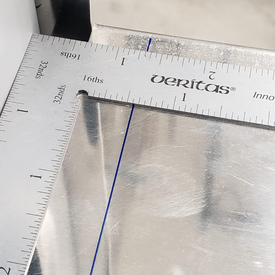
I also started to do a bit of layout for where the fuel tank fastener screws are to be located. In the image below of the plans, the row of rivets that attaches to the upper and lower spar flanges is set to be 5/16-inch up from the edge of the skin (actually from the skin butt-joint line) as your skin may or may not end up right on the line).
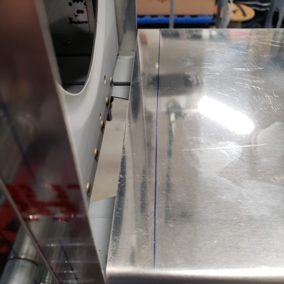
In the picture below, in green Sharpie marker, I measured and drew the reference line 5/16-inch up from the skins butt-joint line.

Next I moved on to drilling the end ribs so that they could be mounted on the tank bulkhead. Note that these end ribs have 10 fastener holes, whereas the ribs in between only have 8.

If you refer to the plans drawing above, you can see that the outboard rib of the tank is directly in line with the outboard end of the tank baffle. That seems like a really good starting point for me, so I’m going to begin by getting this end rib aligned properly first before I move on to the other ribs.
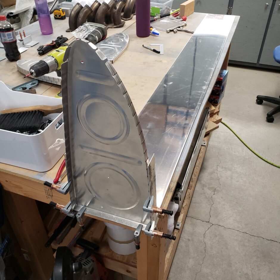
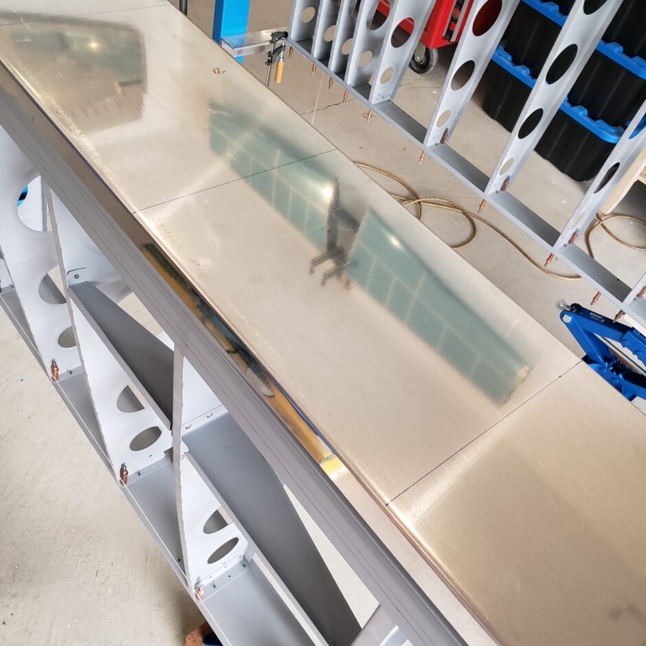
This was easy to align as I just clamped the outboard tank rib to the edge of the baffle, as shown below.

Viewing the picture above, and referring to the drawing below, you can start to visualize how the tank skin, tank outboard rib (and tank baffle) begin to align with the inboard most rib of the fixed leading edge.
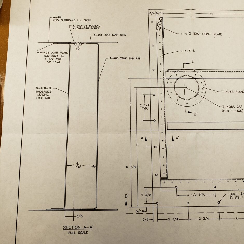
I also drew a line along the inboard side of the tank end rib. I can then use this line to measure (using the drawing above) to help me properly locate the tank baffle position in relation to the inboard rib of the fixed leading edge.
With the pilot holes in the end ribs, it was easy to clamp them in place and then match drill the ribs to the tank bulkhead. As per usual, I used some scrap strips to act as a false skin to help keep the rib aligned on the bulkhead before I drill anything.
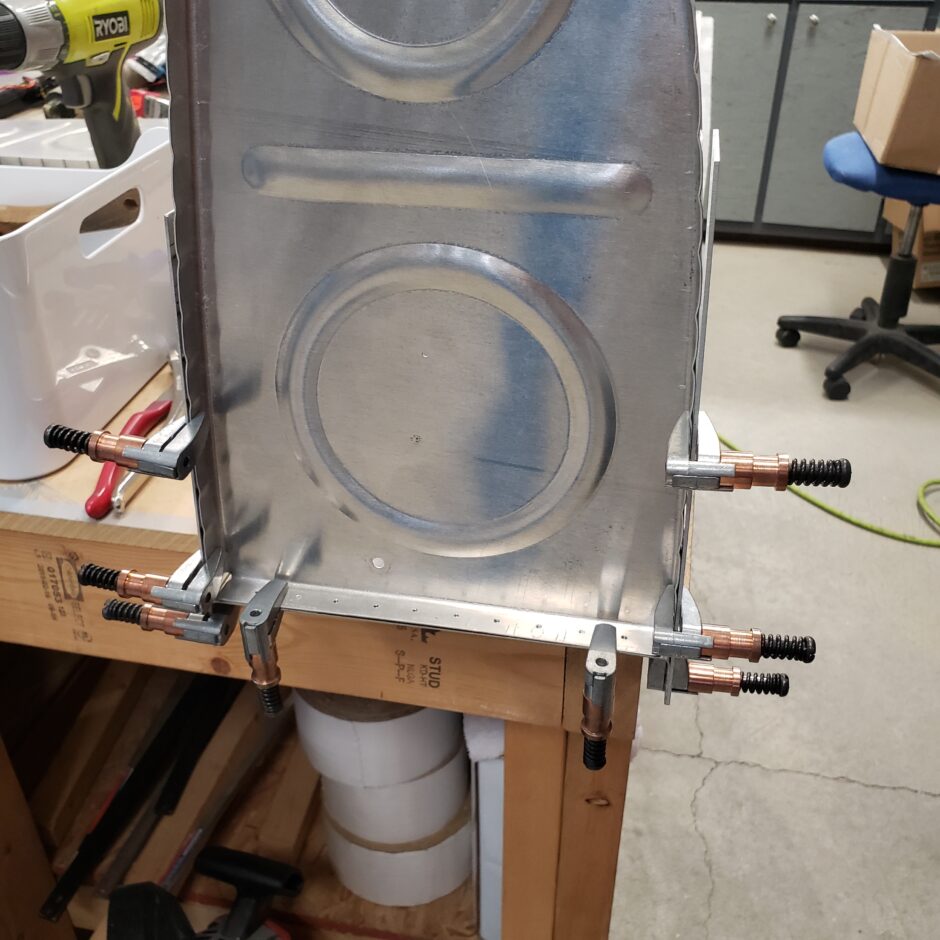
With everything aligned it’s simple to match-drill the holes.

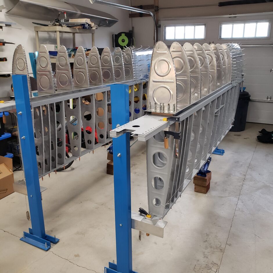
With the end ribs mounted, I was able to get a wee bit of visual progress on the inboard end of the tank. So far, I really like what I’m seeing.
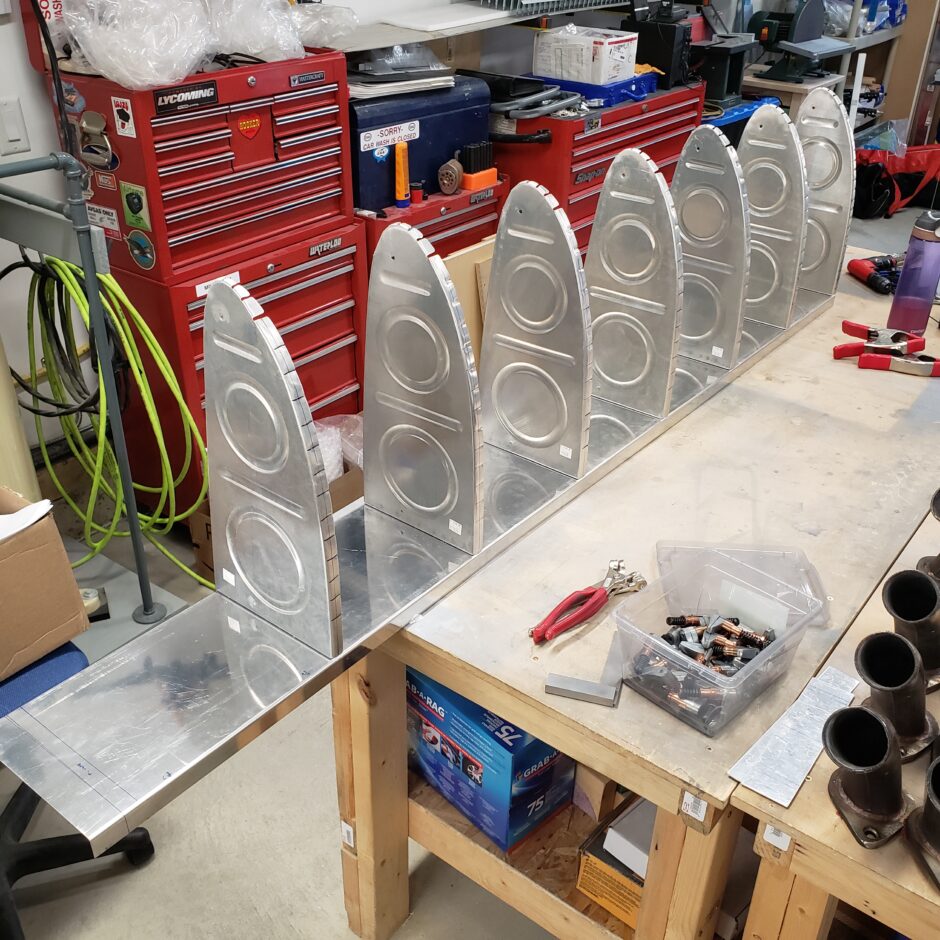
Next I needed to layout the tank rib spacing. The plans showed that the first rib (out from the inboard end rib) has a spacing of 9 3/4-inch. All the other rib spacing, further outboard, is spaced at 10 1/2-inch. As I’m building the 55-USG long range tanks, the tank length is 71-inches. So, when spacing the ribs, they don’t evenly space out at 10 1/2-inch intervals. Due to this, the ribs evenly spaced out at about 9 7/8-inches.
Then for the rest of the ribs, it’s just a lot of rinse and repeat until they’re all drilled.
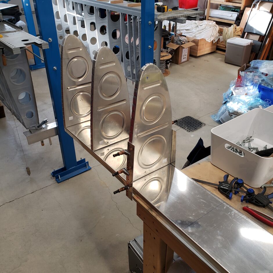
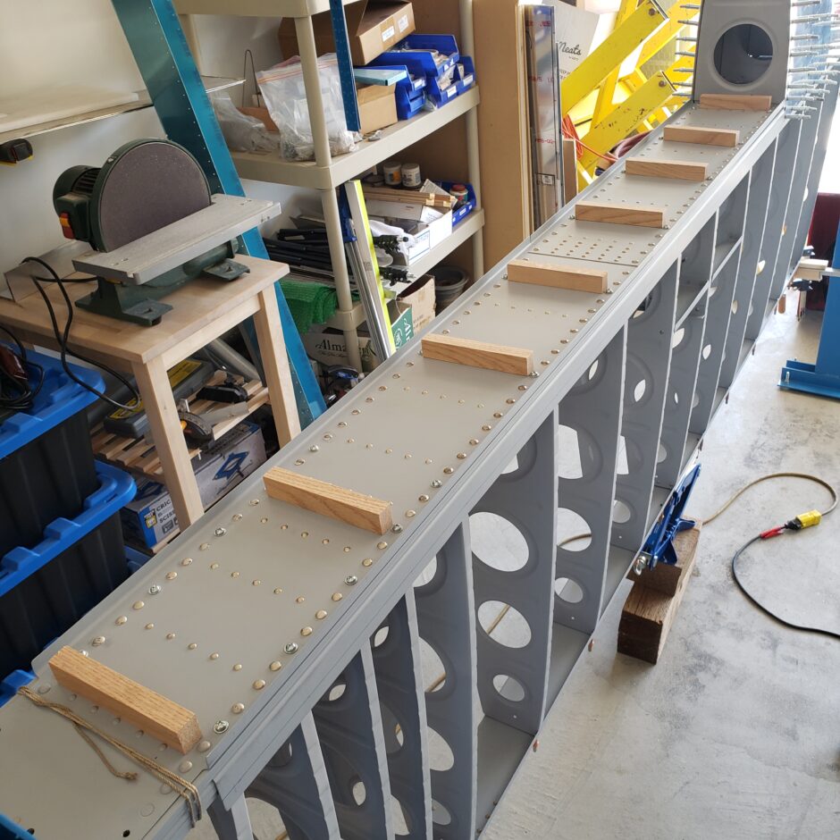
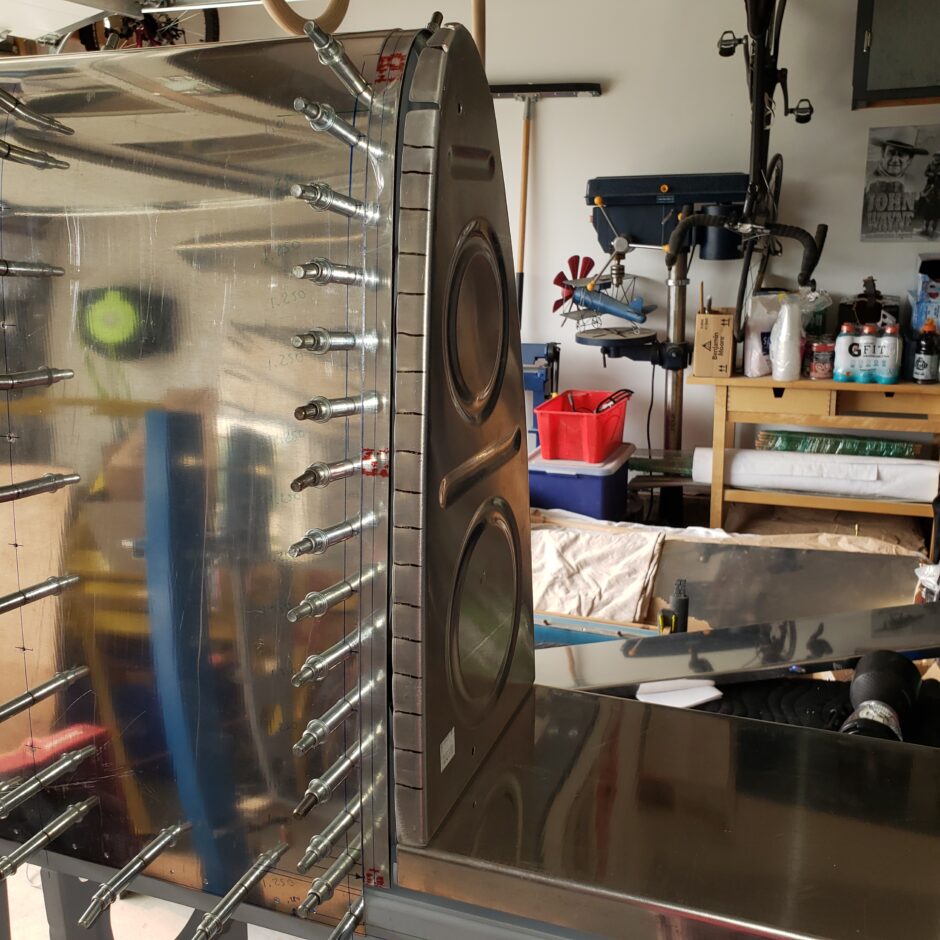
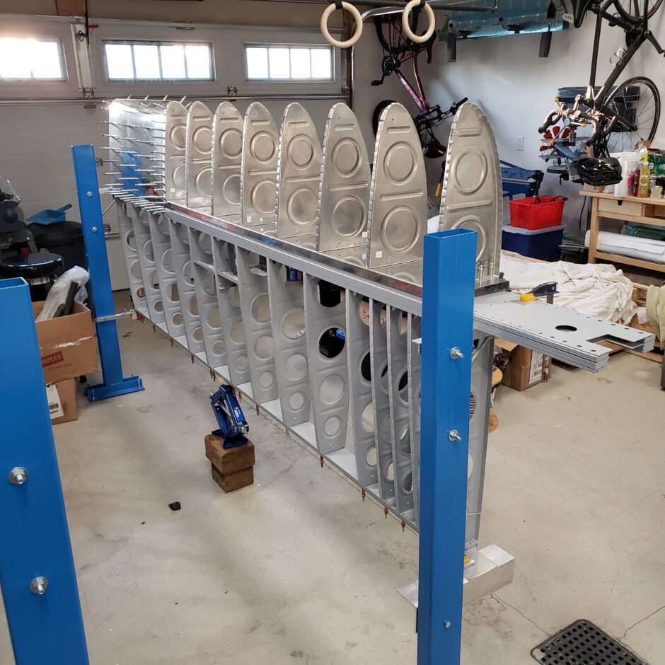
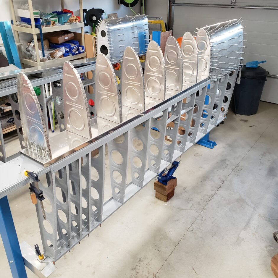
And with all the ribs drilled and clecoed on the tank baffle, it was great to get it on the wing and see the progress.
That’s all for today folks! Please comment. I love to hear from my readers. Thanks again for coming along for this ride, you make my work worthwhile.
Leave a Reply