Today I’m working on the left tank rear baffle. As these tanks I’m building are the optional 55 USG extended range fuel tanks, I’ve decided to add access panels in each of the tank bays should I need future access. The reason for this is because the tank is so long, you just can’t reach into the middle of it, even if out pulled out some ribs in a repair situation.
So in the picture below, you can see that I identified the center of each bay and marked a circle for the cutout. For the access panels, I’m using the same measurements as the T-407 reinforcement ring and T-708 access plates which are on the inboard ribs for the fuel tank sender mounting.

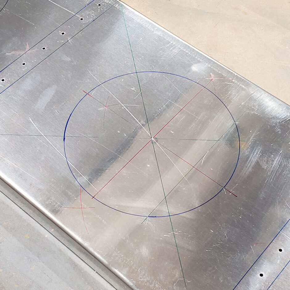
At this time I also located the center of the inboard rib, as I have to also cut that out for the associated access panel in this location.
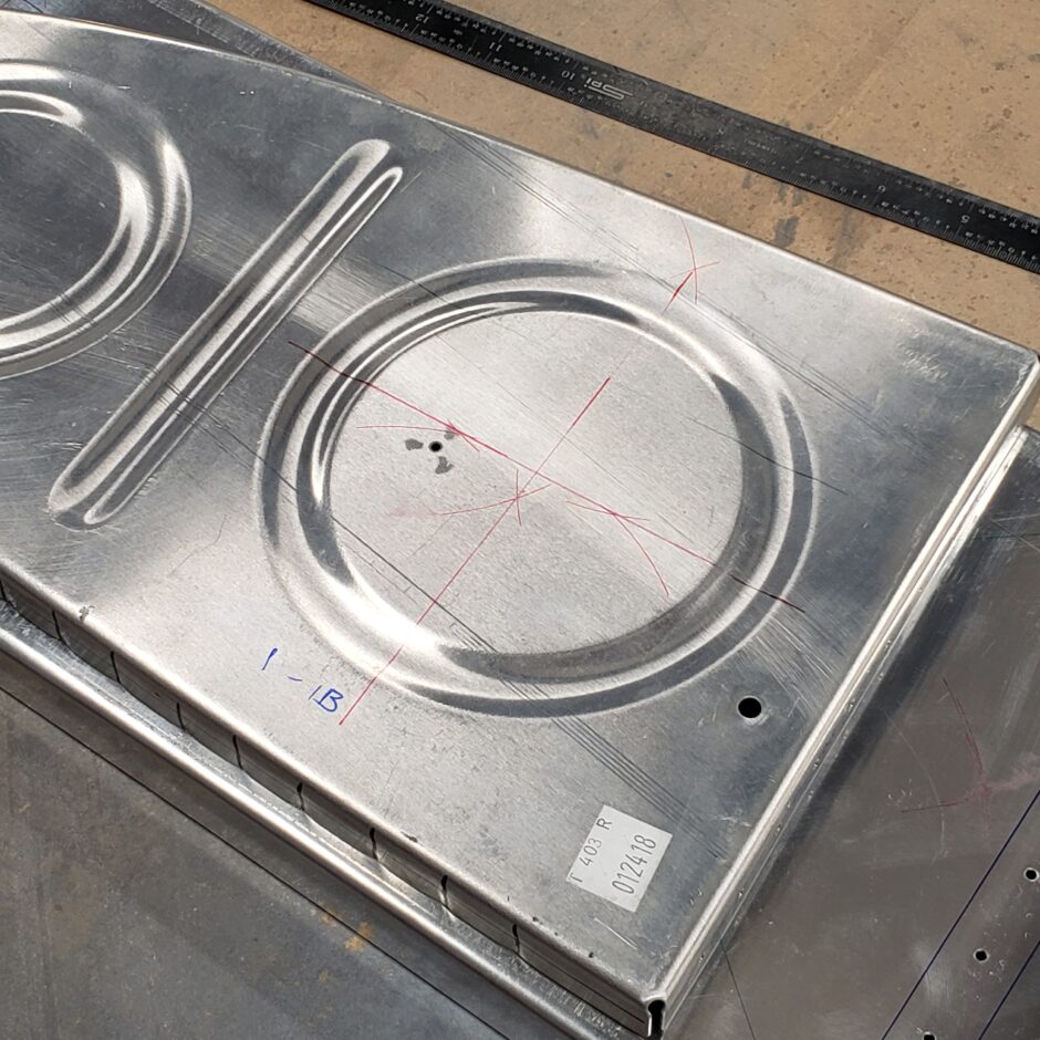
Using the fly-cutter in the drill press, the rear baffle access holes were quickly and accurately cut. I know a lot of people hate using this tool, but for what it’s worth, it works really really well. Just keep your hands clear and set your drill press speed to the lowest setting and you’ll be fine.
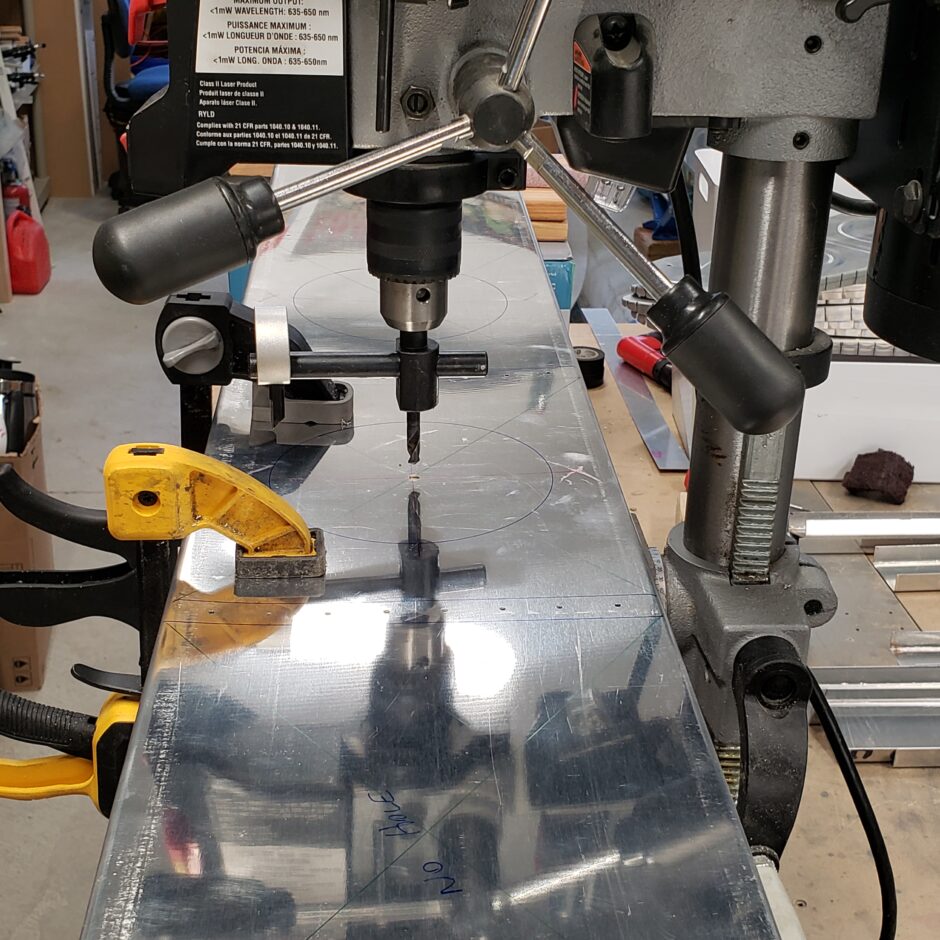
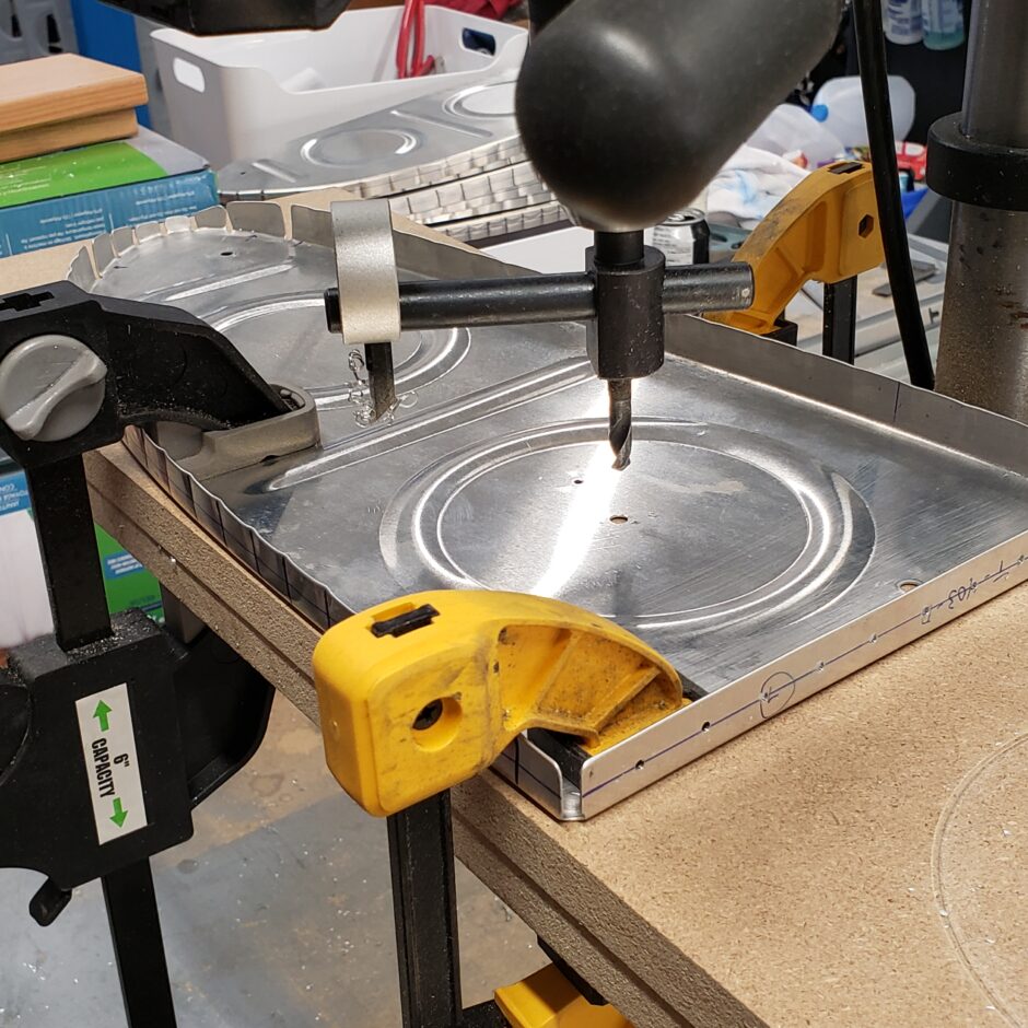


Oh boy these parts tanks are going to be big! I’m about 5’10” so you can get an idea of the size these tanks are going to be.

Here’s the assembly back on the wing.
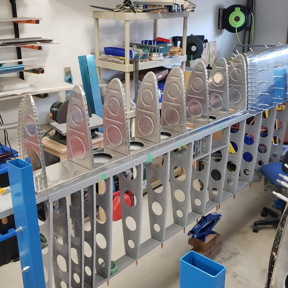
The next task at hand was to get the skin drilled to the ribs. Previous to the picture, I had already drilled all the rivet holes in the skin. In the picture below, I now have the assembly in the fuel tank holding fixture, with the rear baffle strapped to the skin, holding all the ribs fitted tightly into the leading edge. I also found that all the access panels are extremely helpful in allowing me to use a rubber mallet to tap the ribs into place, so that I can get the flange centerline visible in the skin pilot holes for drilling.
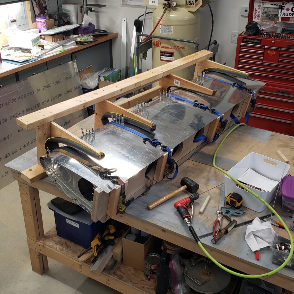
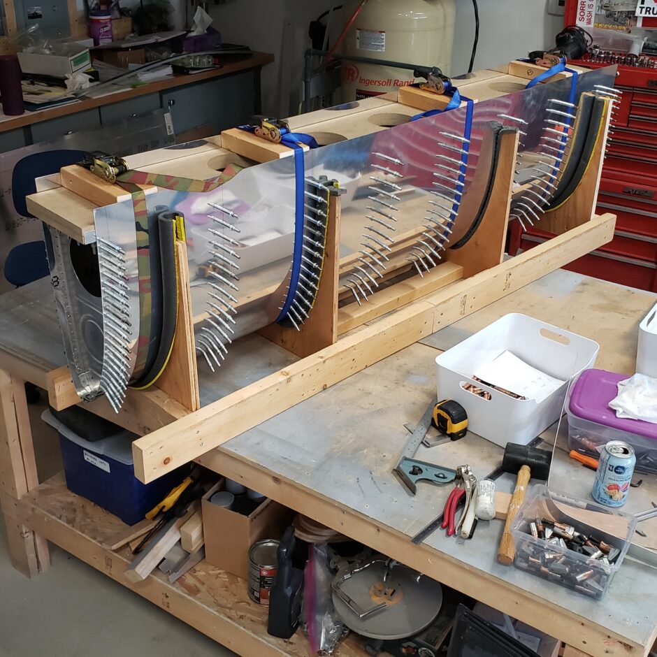
With the skin drilled and clecoed to the ribs, the entire assembly can then go back on the wing, where we’ll get the assembly prepared to be drilled to the spar web doubler (W-6B) on the forward side of the spar.
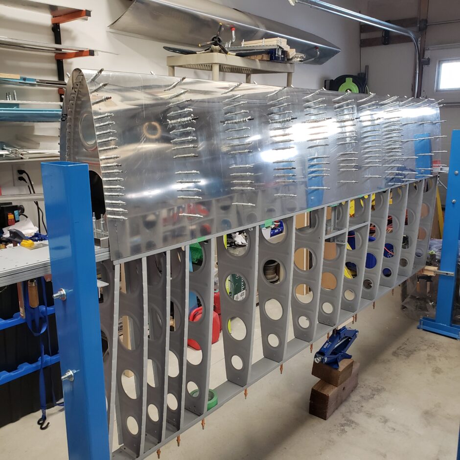
As you need to lift the skin on one side of the tank to accomplished this task, you therefore can’t keep the skin strapped down. So the way you keep the fuel tank in perfect alignment (to keep the leading edge flat with the fixed leading edge skin) while drilling the rear baffle, and skin to the spar doubler, is by tacking the tank in place with some pop-rivets.
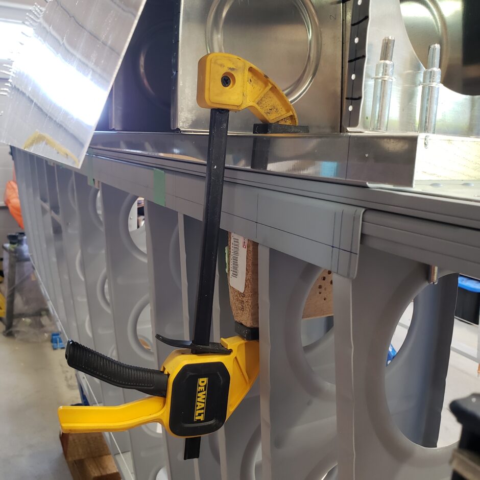
I clamped the rear baffle to the spar and wooden spacers to ensure it’s down tightly, as the straps would pull it down. Then I drilled to ensure that I’m in the center of the spar doubler flange.
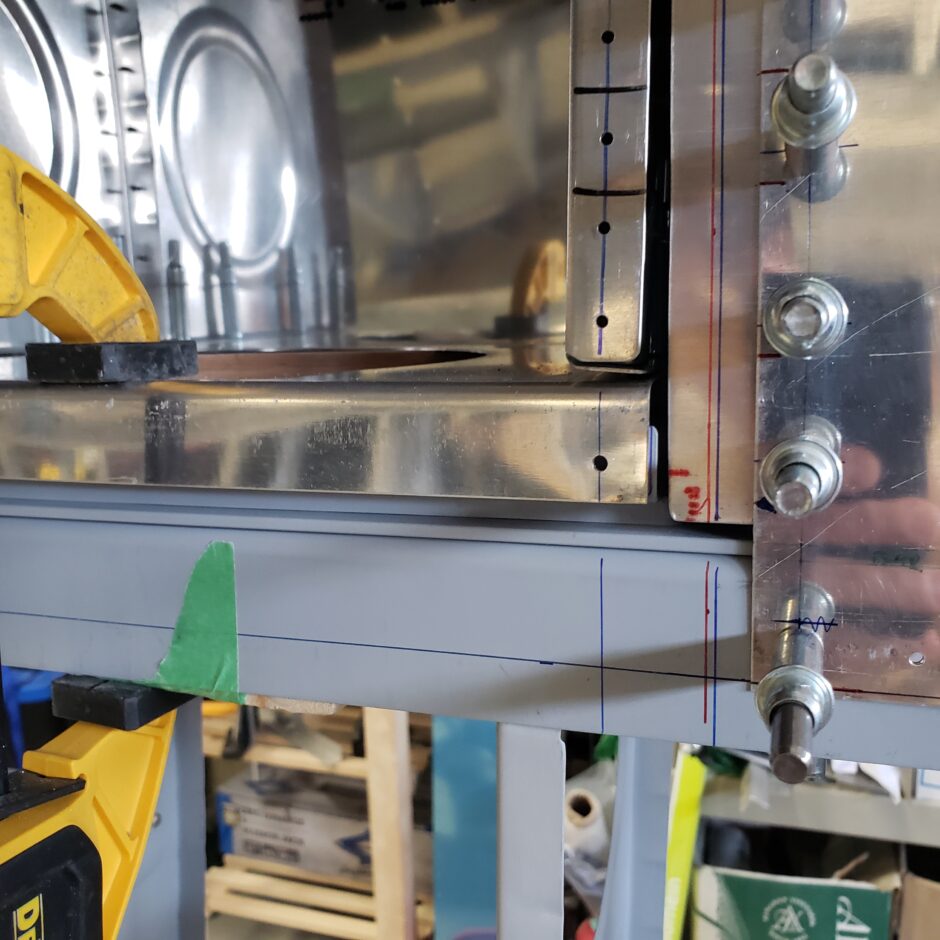
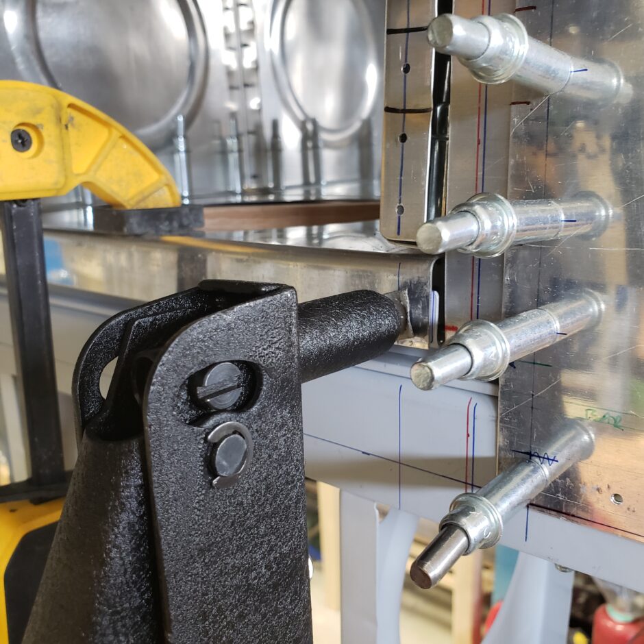
I added 4 rivets along each side of the tank flange to hold it in place (upper and lower). Also make sure these rivets are located appropriately with the proper measurement, as this will end up being an attaching screw hole!!

Here is another shot of how I clamped the rear baffle to the spar to ensure that the assembly was tightly in place.
I didn’t take any pictures of drilling through or showing the spacing of the screw holes on this assembly, as this material has been previously covered that in detail in an earlier post for the right fuel tank.
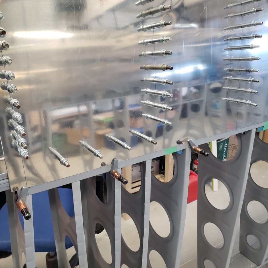

With both sides of the rear baffle drilled to the spar doubler, the next step was to layout and drill the row of rivets which attach the rear baffle to the skin. Again, this was covered in detail in an earlier post for the right wing.
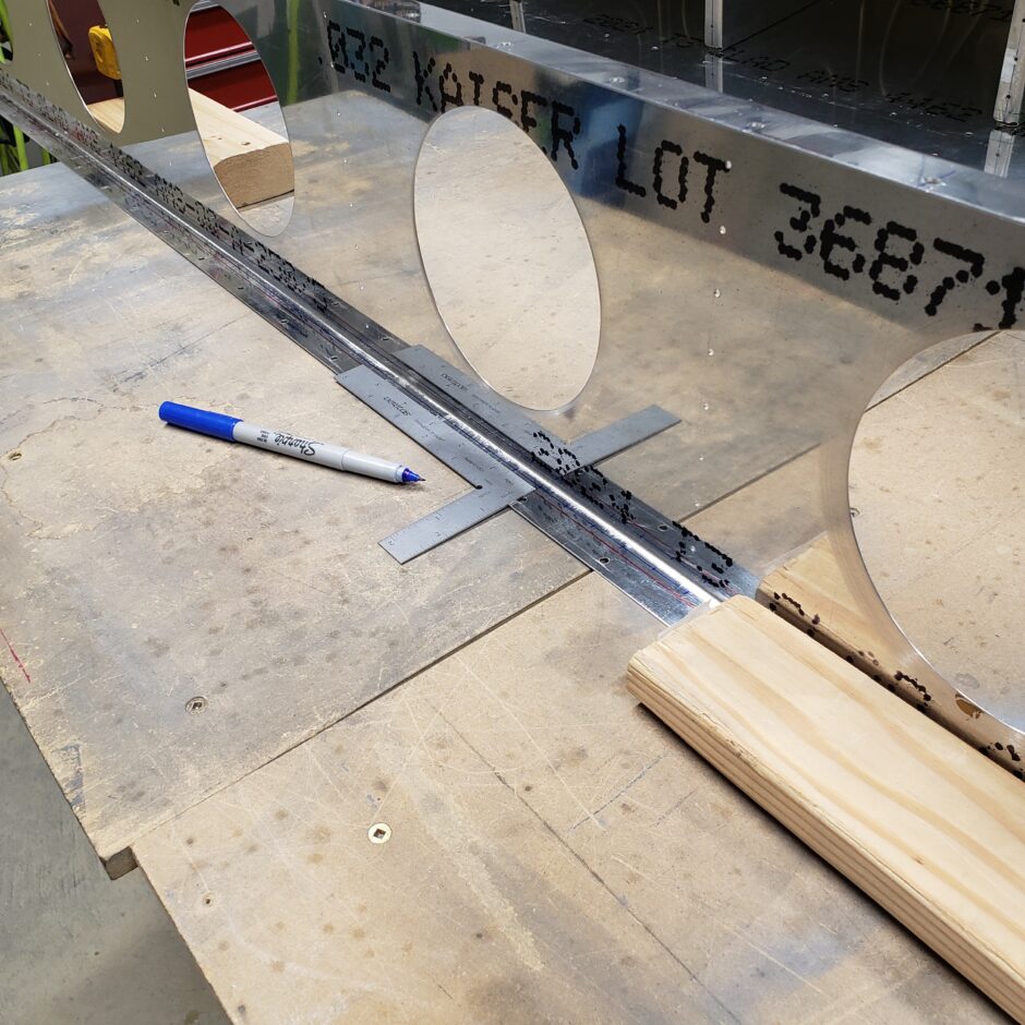
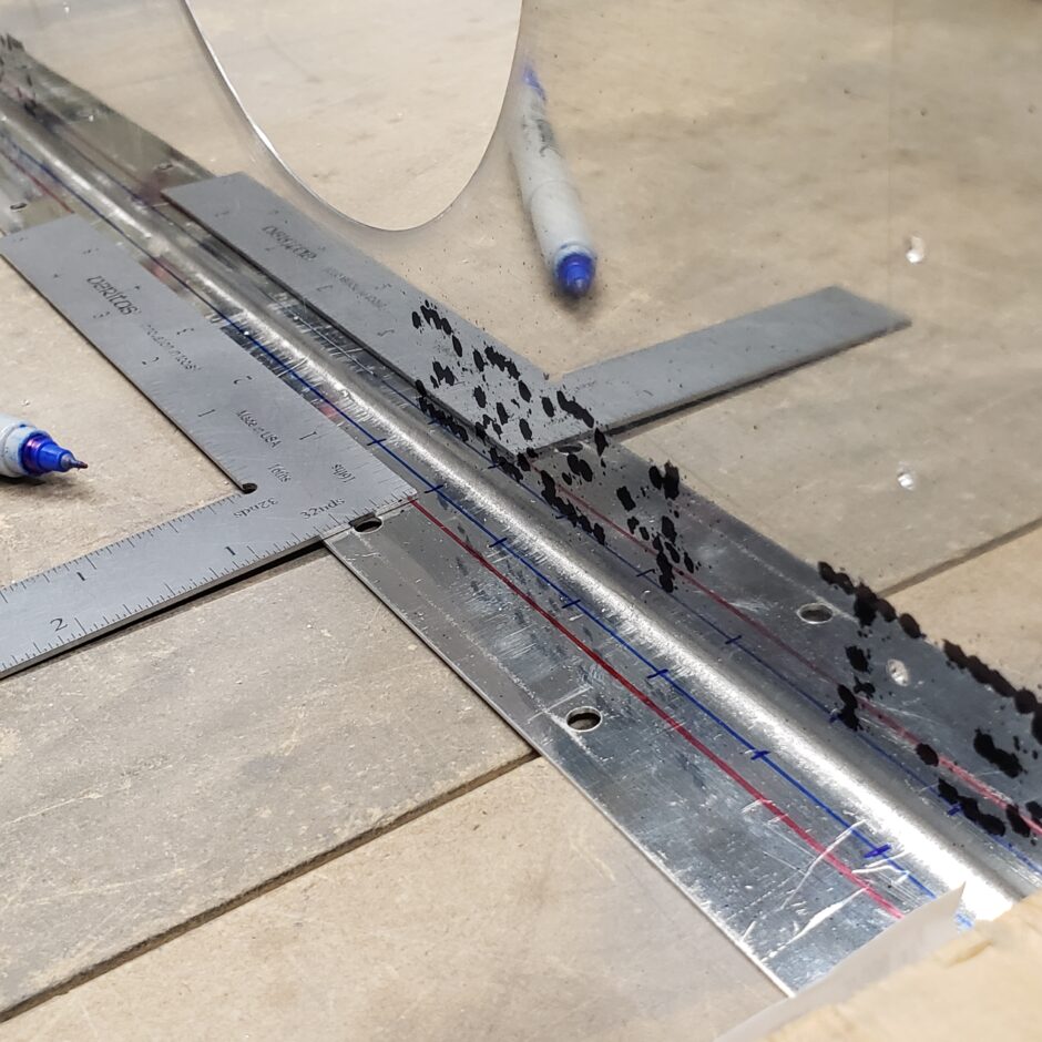
It’s a bit tricky to drill these rivet holes, I found that using a piece of board clamped along the flange helped to hold things steady while I drilled.
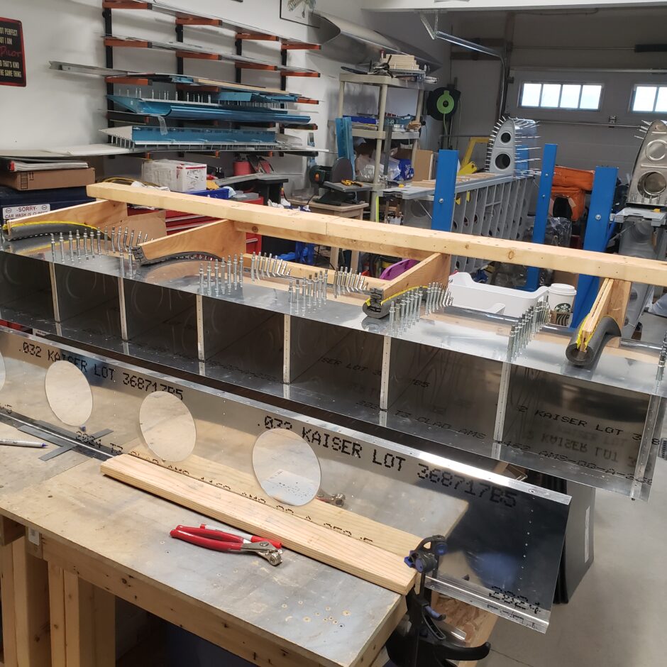

With the rivet lines on the rear baffle drilled, the entire assembly can then go back together, and you can match drill the rivet line to the skin. At that time, you can also drill the second line of attaching screws which go through the main spar web. Again, this has all been covered previously, so I’m not going to detail the process again here.
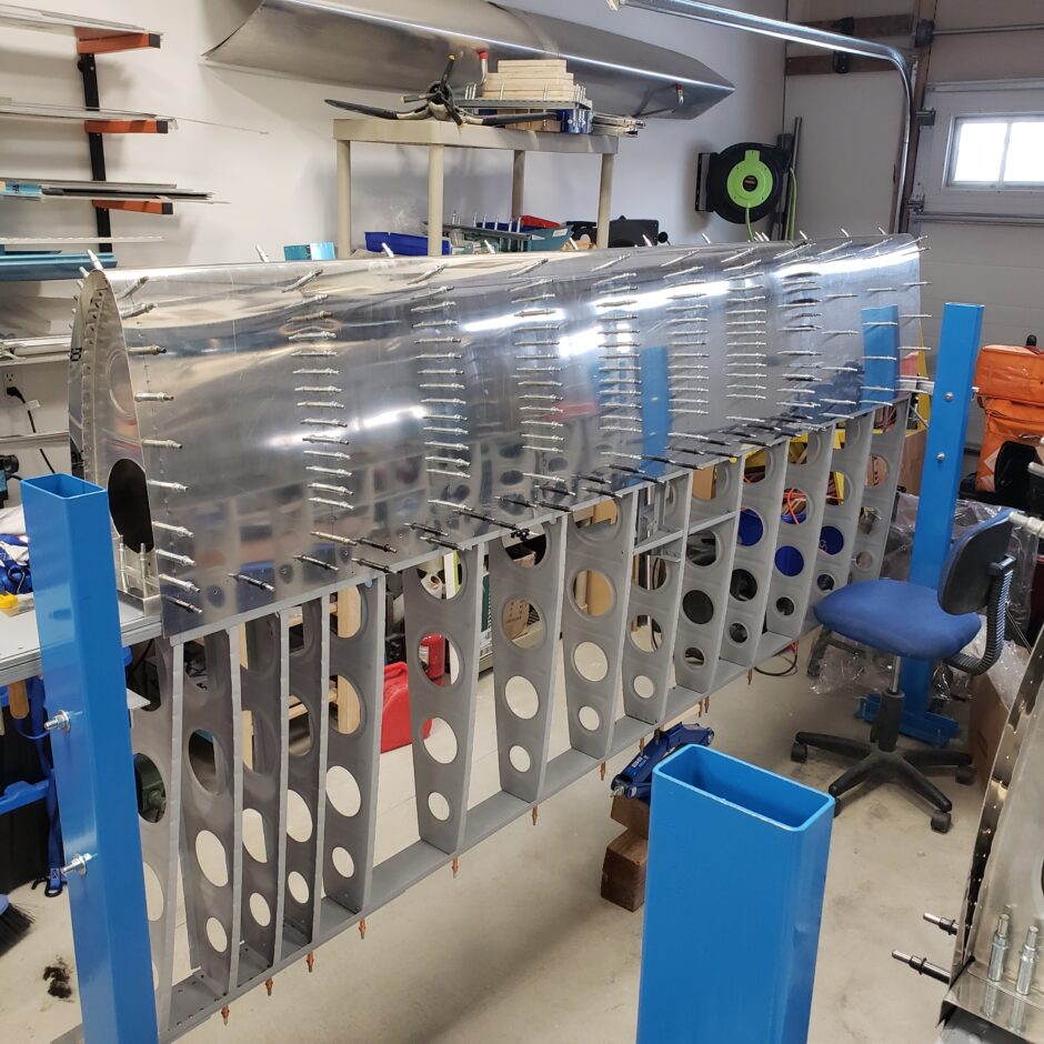
Well, that’s all for now folks. Please comment. I love to hear from my readers. Thanks again for coming along for this ride, you make my work worthwhile.
Leave a Reply