Greetings, this post is going to detail the work accomplished for the left wing fuel tank. I’m not going to go into too much detail, as much of those details have previously been covered as I worked on the right tank assembly.
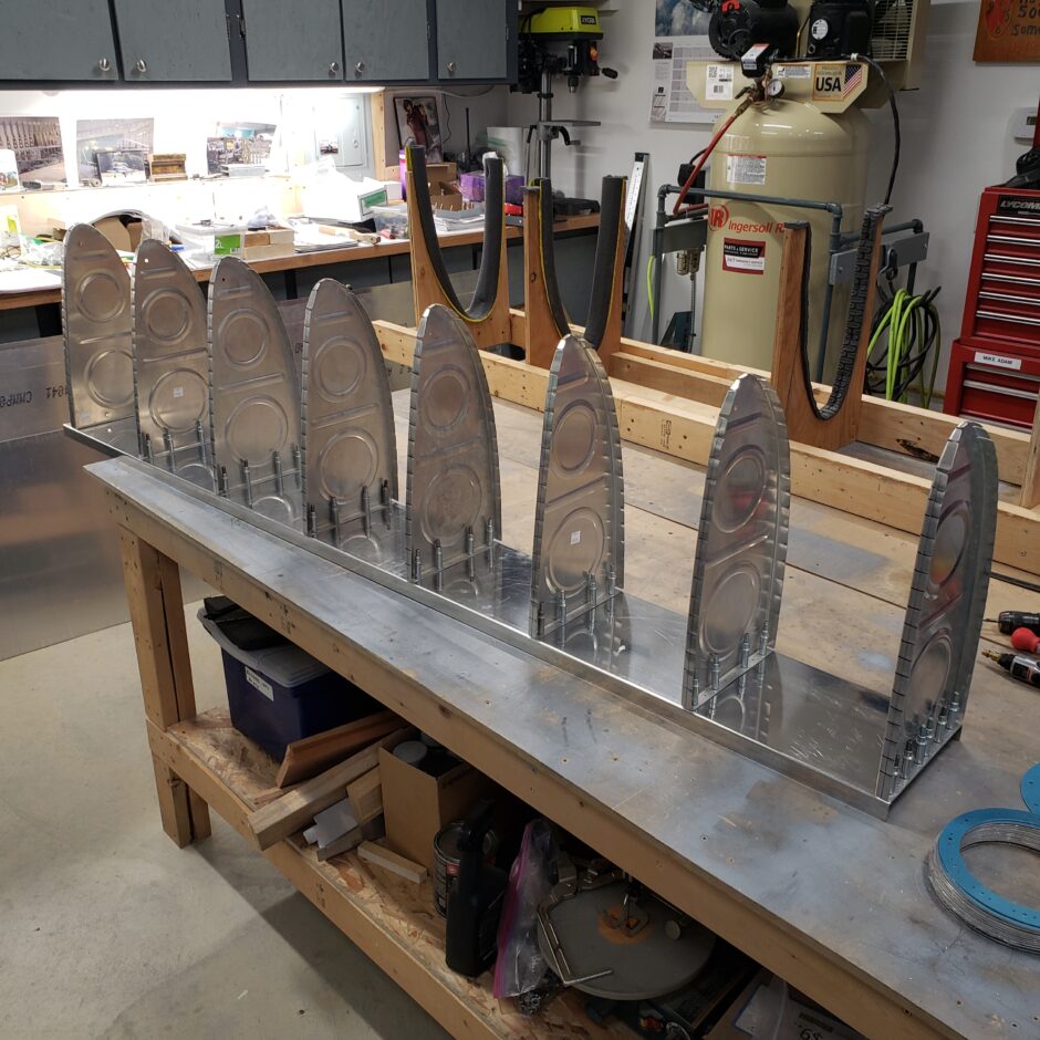
I started off with the wooden spacer blocks used to support the fuel tank rear baffle in place until the point where it is drilled and clecoed to the wing spar, when it can be self supporting.
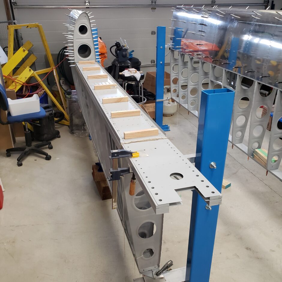
The next step was getting all the ribs located and drilled to the rear tank baffle.
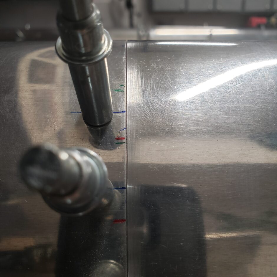
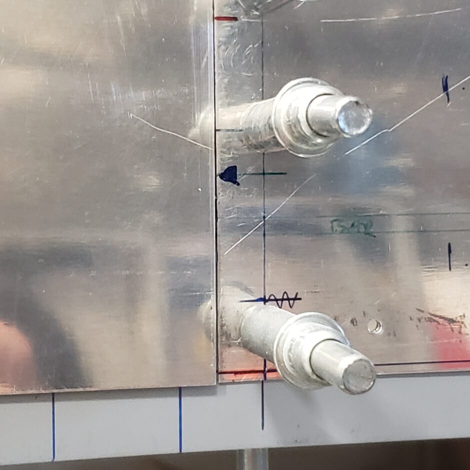
With the ribs and baffle assembly in place on the wing, and appropriately located for position. When that is set, you can then transfer the rib flange centerline, to the spar to make the rib rivet reference line which will be used to transfer the tank skin, when it’s overlaid.
Don’t forget to also mark the centerline on the W-423 joint plate flange which attaches the fuel tank to the fixed leading edge.
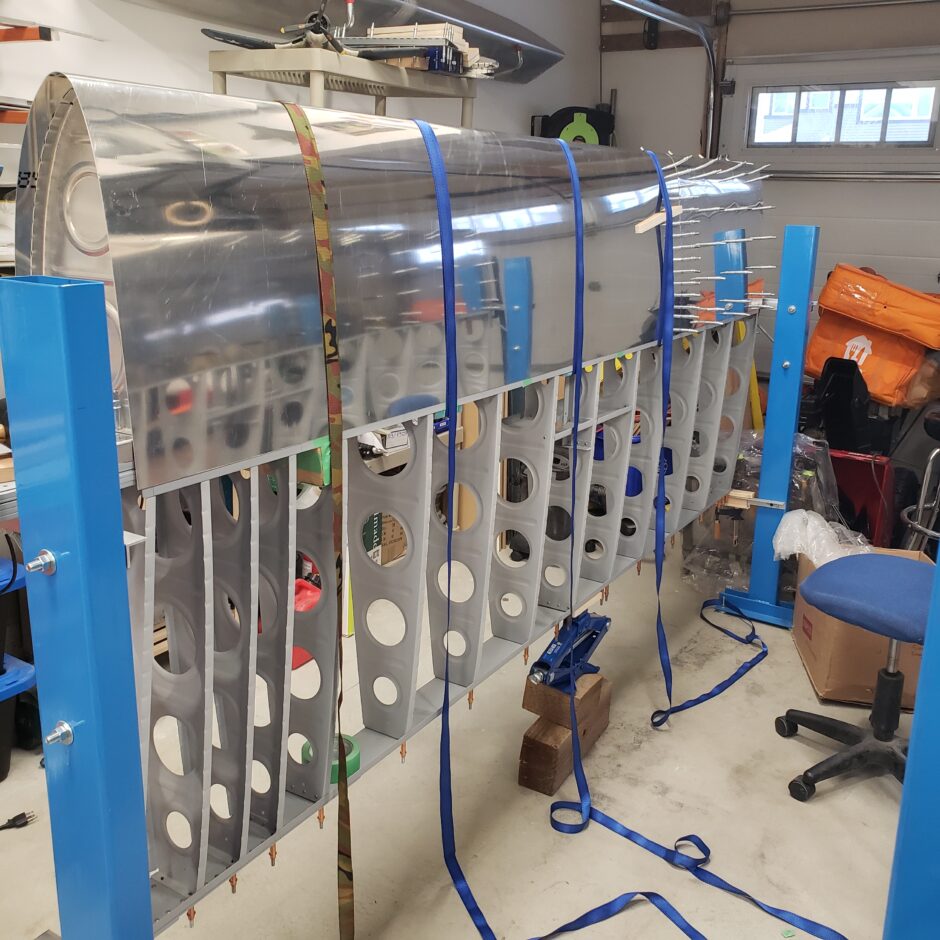
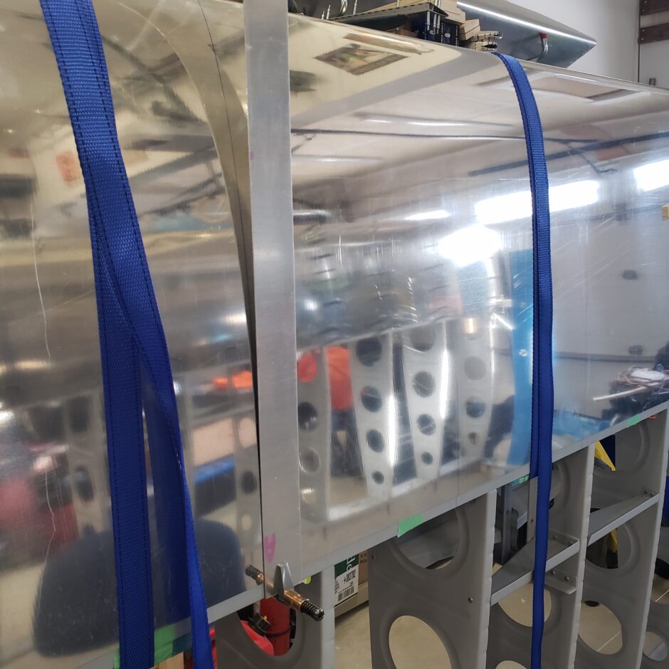
With all that layout work done, you can then get the skins on, and strap them down.
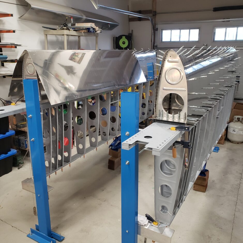
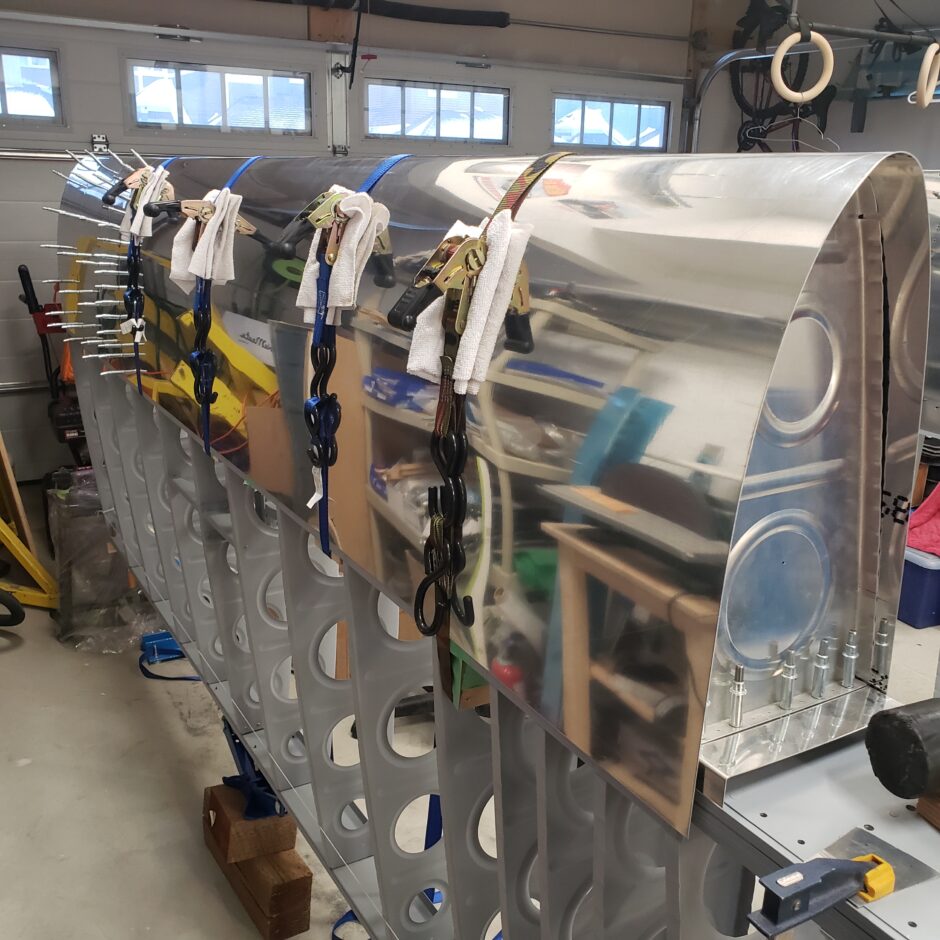
The next big task, is to ensure that your fuel tank skin is evenly mated to the fixed leading edge skin. Here you’re aiming for about a 1/32 inch even gap. This also may require identifying any high spots of the skin along that butt joint, removing the skin, filing it down, putting the skin on and starting the process all over again, and again, until you’re happy with the butt joint in this area.
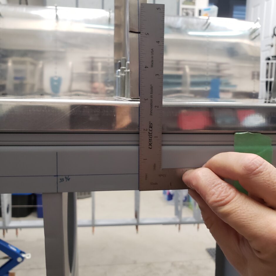
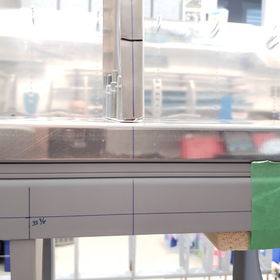
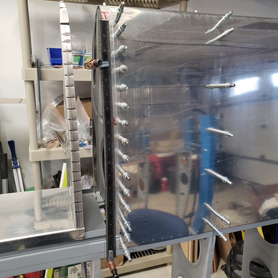
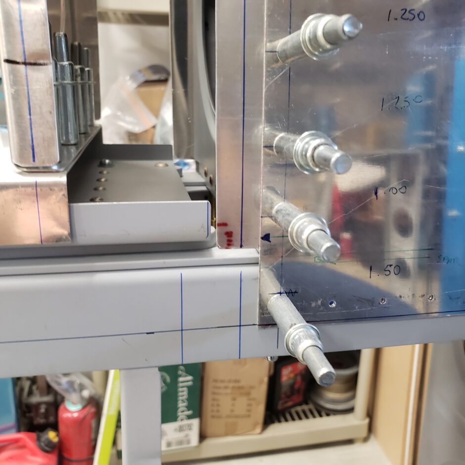
At this point, the fuel tank skin is properly located, and you can then start the layout for the rivet lines along the ribs. I used a straight edge to pick up the references lines I previously made on the spar. Then made vertical lines up the fuel tank skin which will receive the layout marks and spacing for the rivet holes.
I then taped a sewing measuring tape along the tank skin and used that to measure out the rivet spacing.
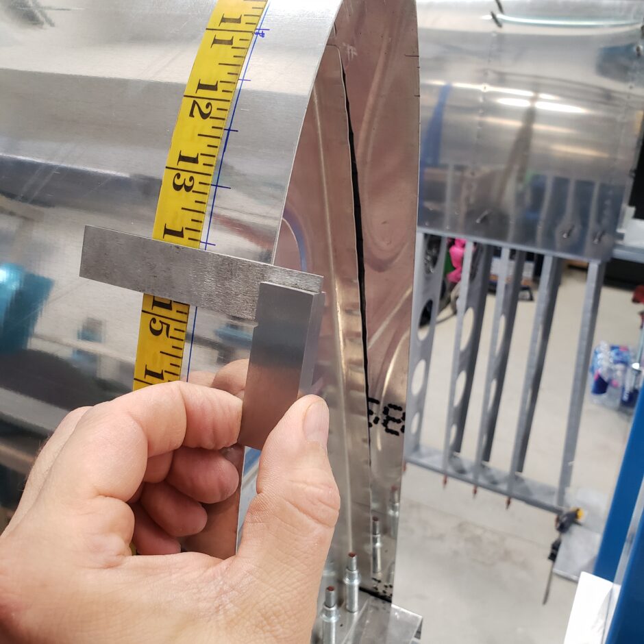
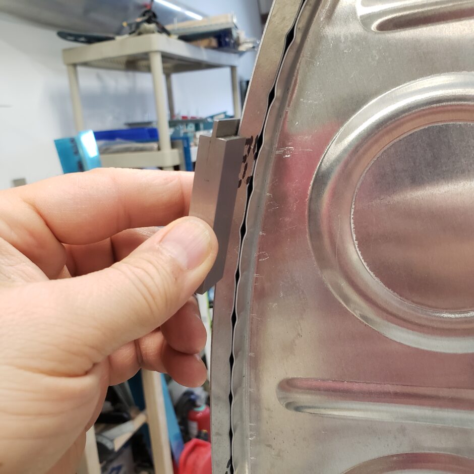
I also found it helpful to use the machinists square to help ‘eyeball’ and visually confirm the rivet spacing lines were located on the rib flange, and not in the fluted areas.
Well that’s all I have for today. Please comment. I love to hear from my readers. Thanks again for coming along for this ride, you make my work worthwhile.
Leave a Reply