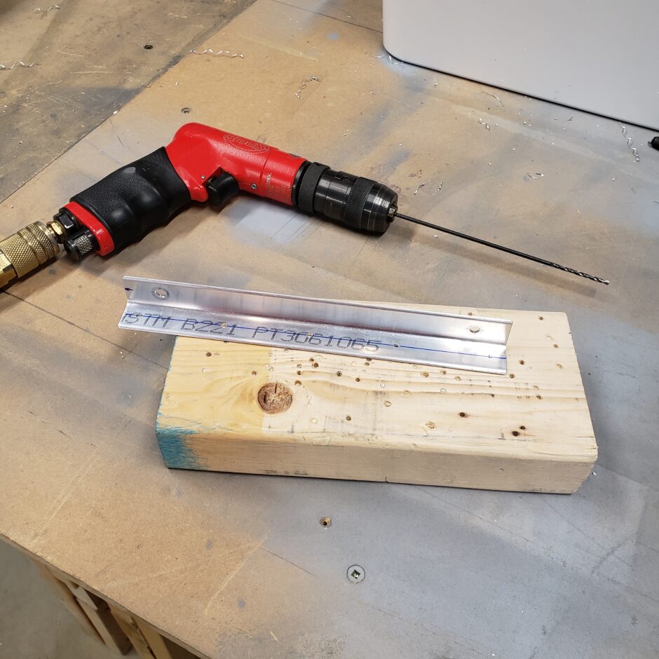
It’s time to start building up the left wing skeleton and I started by pilot-drilling the rib attach angles. These angles need to be drilled with 5 holes. The plans talk of building a drill template that can be used on each angle to ensure they are the same. I opted to just measure for proper edge distance and use the rivet fan to space the rivet placement. It’s easy and I figure just as accurate.
In the picture below, I am starting with a #40 pilot drill as these holes will eventually be opened up to #30 for final riveting. I started on the inboard most rib angle and worked my way outboard.
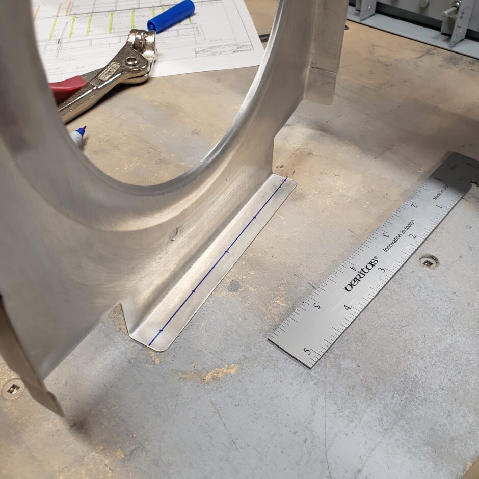
As shown in the picture below, some of the ribs will have a forward flange that gets riveted to the main wing spar. Again, I just marked out the proper edge distance and spaced the rivets as per the plans. Lots of repetition but it’s all straightforward.
Then individually (by wing rib location) I clamped the rib in place, centering it as best as I could (up and down) between the main spar flanges. When I was happy with the placement, I match-drilled the pilot-drilled rib angle to the wing rib.
With the rib drilled and securely clamped to rib attach angle, I ensured I had the rib vertical (or 90-degrees to the spar) and then drilled the forward rib flange to the spar. Be careful here, as you are only drilling through the aft spar face…not all the way through the spar!
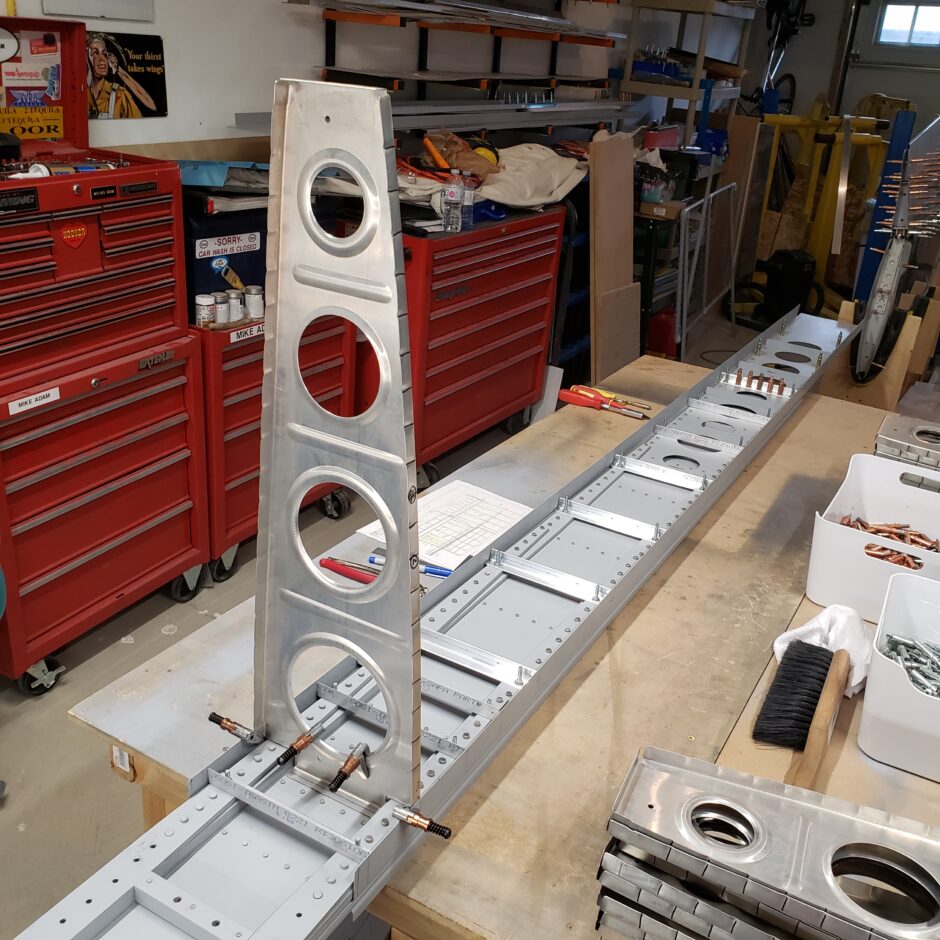
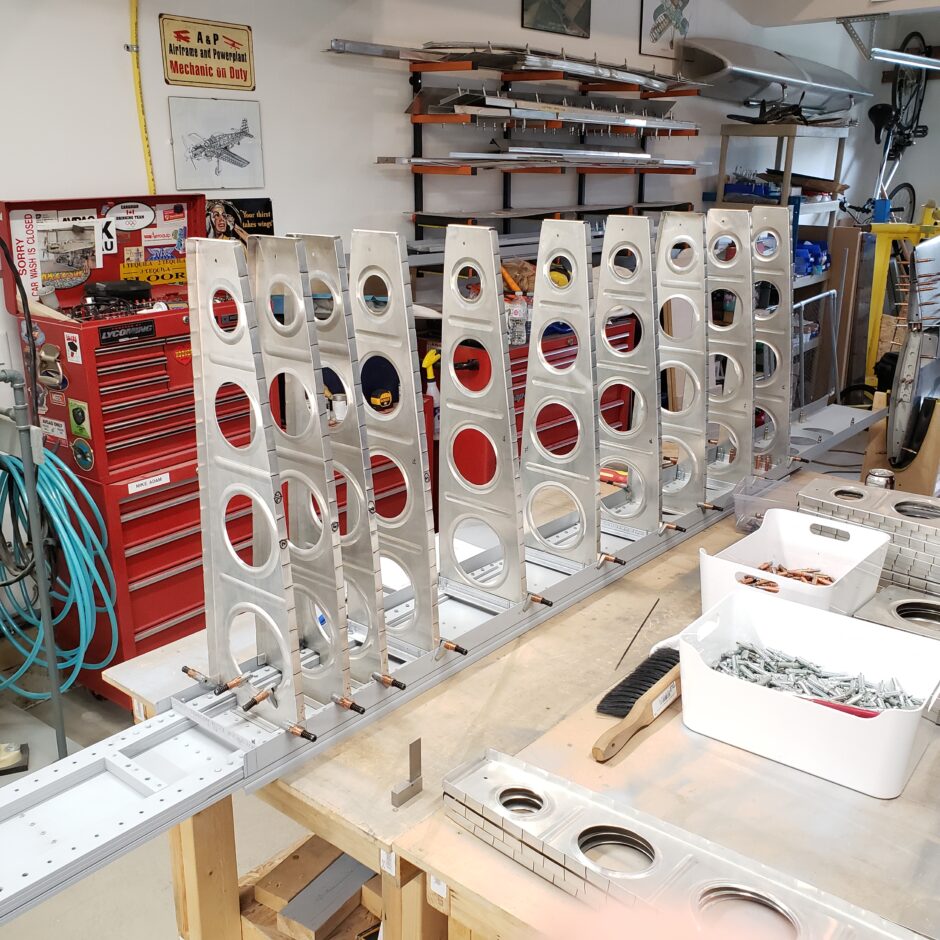
Progress is slow but steady. Still a lot more ribs to get in place.
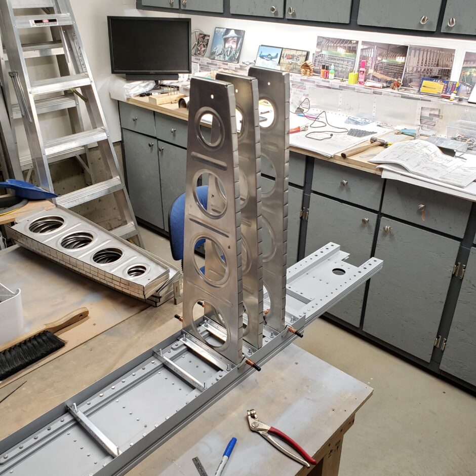
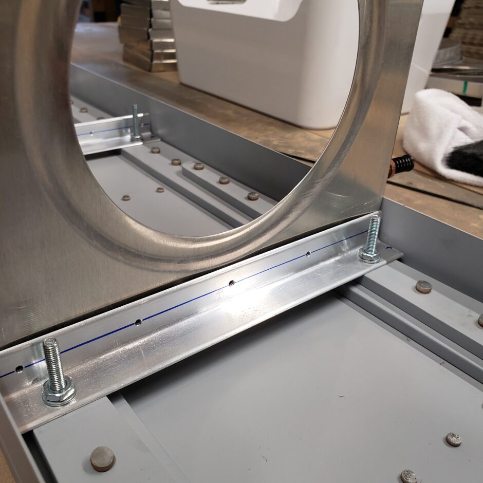
Here is a close up of a rib attach angle and the pilot holes.
With the formed lightening holes, you have to get a bit creative to clamp the rib tightly to the attach angles for drilling. As you can see below, I used a small clamp and a scrap piece of wood, then 2 cleco clamps on either side. This worked out well.
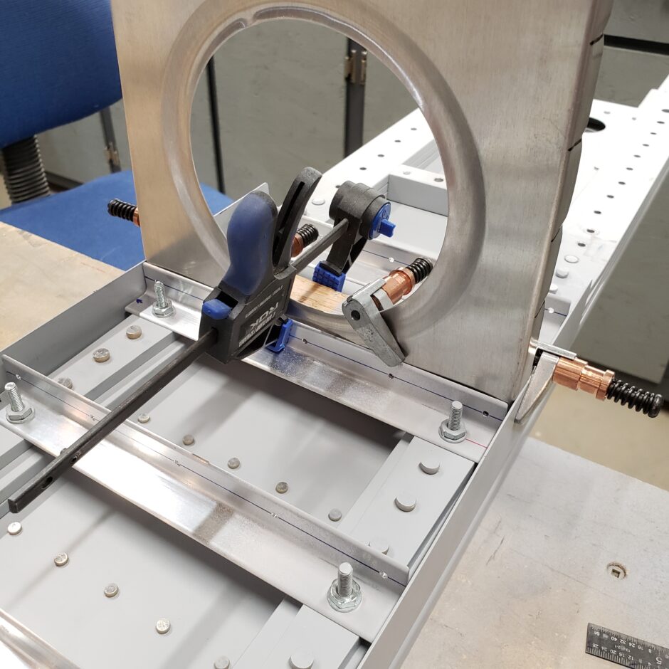
Here’s another shot of clamping a rib and one that is clecoed.
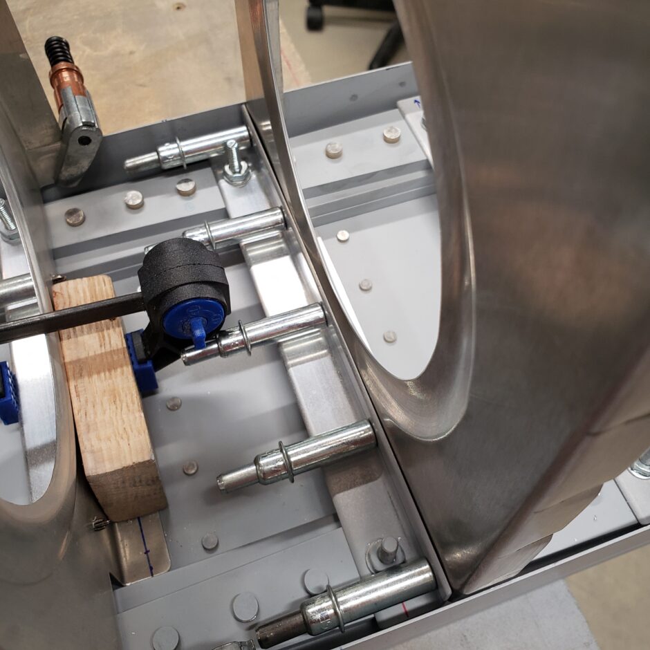
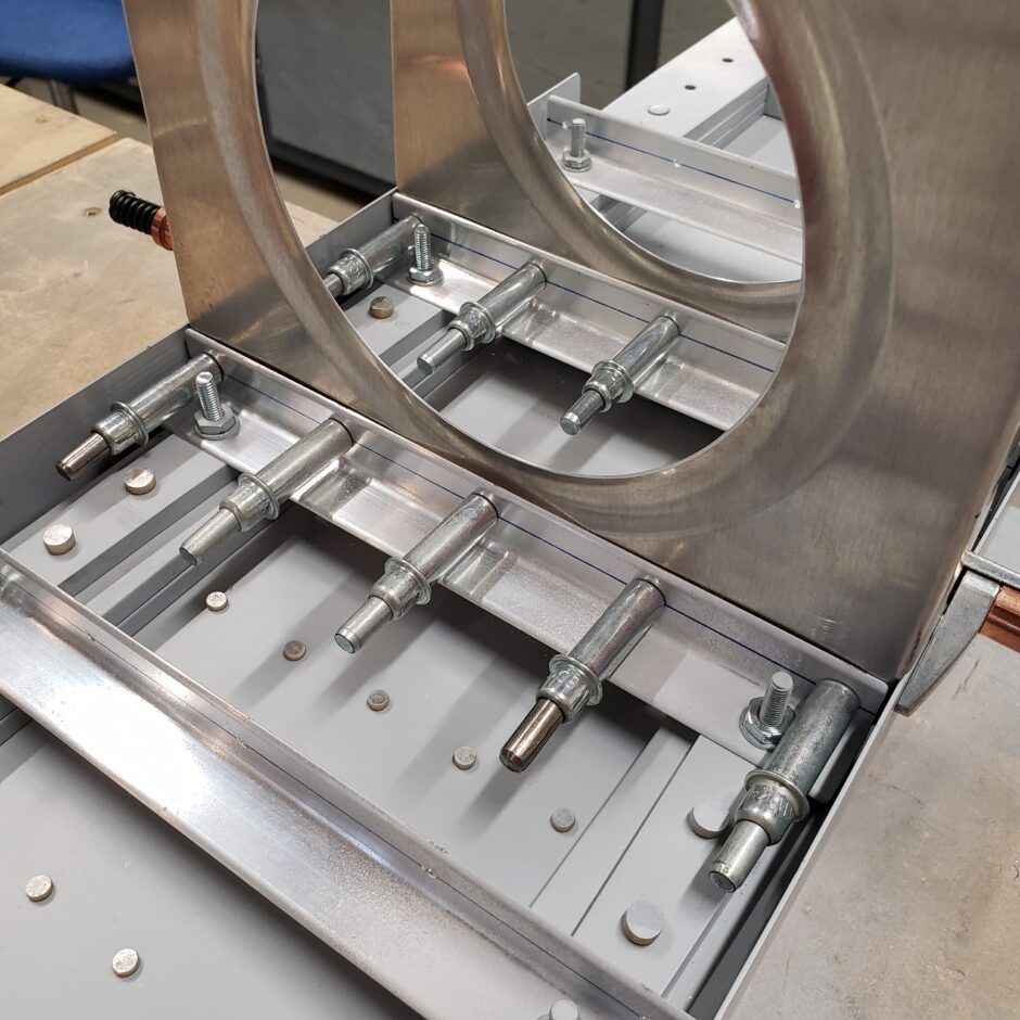
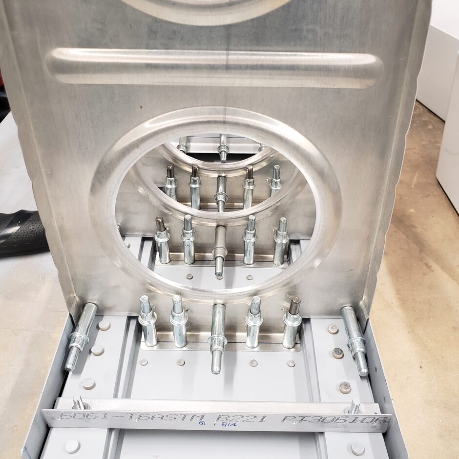
You will notice that some of the ribs have flanges that span the RV-4 wing spar lightening holes. Not much you can do about this, just be mindful of them. This is a good reason why not to work to far ahead and not pre-drilling the forward rib flanges until you have them in situ. As you can see in the picture below, I couldn’t drill any of the flange holes on this rib.
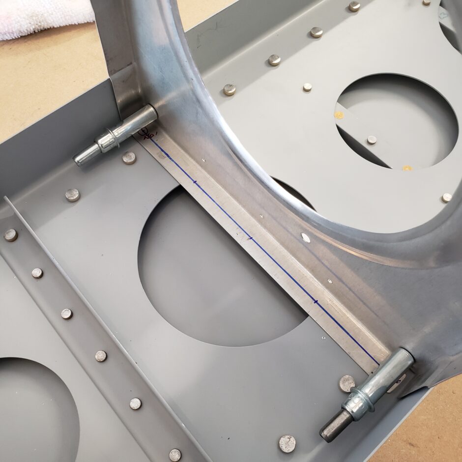
Here is another rib where I could only drill the 2 mid holes omitting the outer two holes. The center hole was also omitted because it would give me edge distance issues. Again, not much I can do about that.
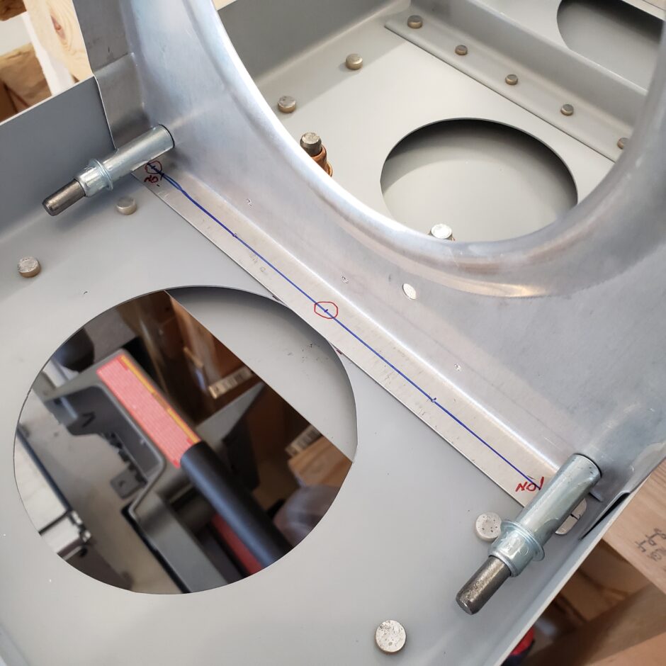
In the picture below, you will see that I flipped the #9 rib to be mounted opposite to the plans direction. This was based on comments made on Vince’s Rocket build log that expressed that it would make the aileron bellcrank installation easier.
UPDATE: From personal experience further along in the wing build, this mod of installing the # 9 rib in backwards / opposite did not work for me. This created all sorts of grief. In the end I resorted to keeping the installation AS PER THE PLANS! Also shown in the picture below, the rivet that is identified as # 9 is where the rib should be located as per the plans – that is the correct location. Due to trying to make this mod work, my rib ended up being one rivet outboard of the standard position. Like I said, this mod has caused me a bunch of grief that I ended up having to work through in coming posts.
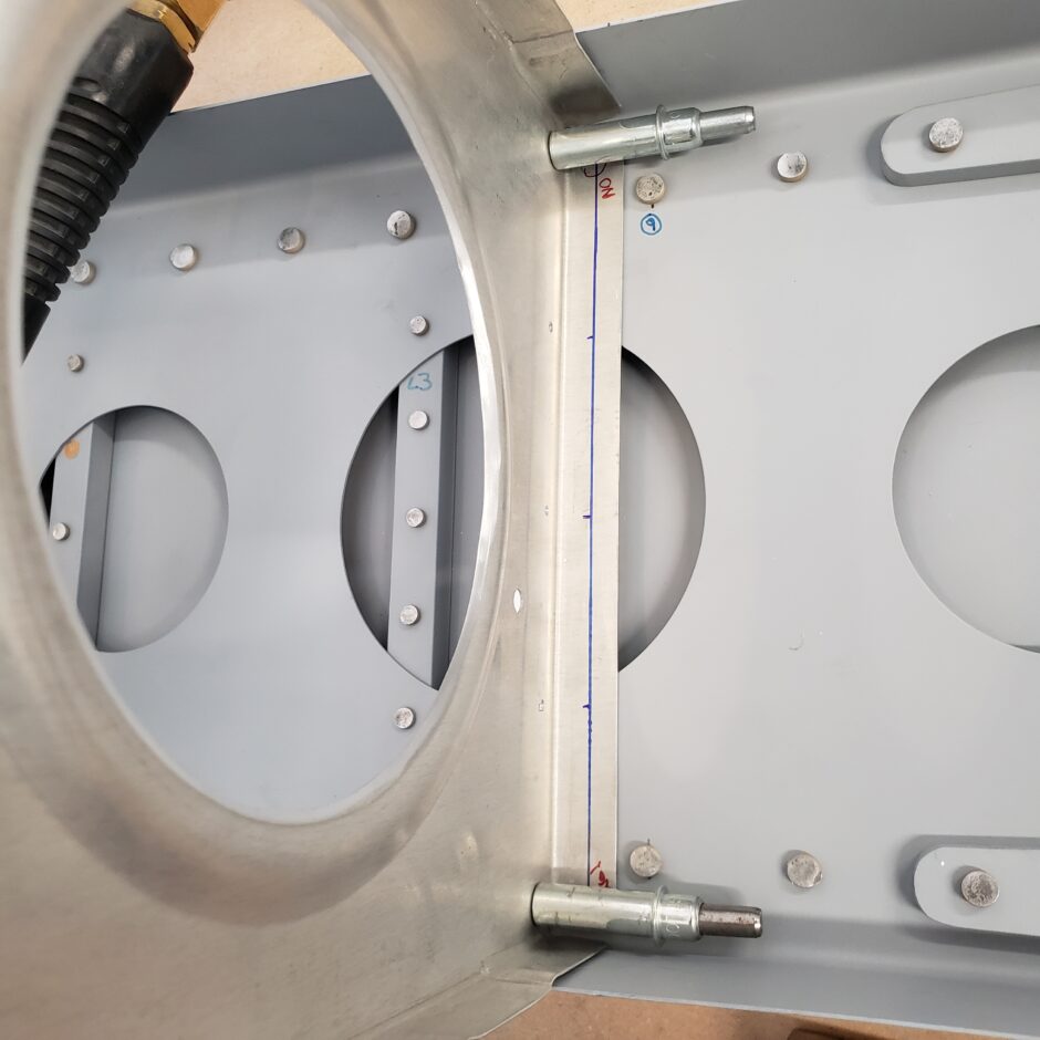
When drilling the forward rib flanges to the spar, I found using a long #40 drill bit work very good here. In most situations you would be able to move the rib off to the side to be able to drill the hole squarely, however here, you want to keep that forward rib flange tight against the spar when drilling it.
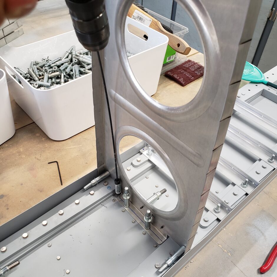
Again, lots of repetition but eventually all the ribs will be located and drilled!
Please comment. I love to hear from my readers. Thanks again for coming along for this ride, you make my work worthwhile.
Fabulous job, fun to see it progress!