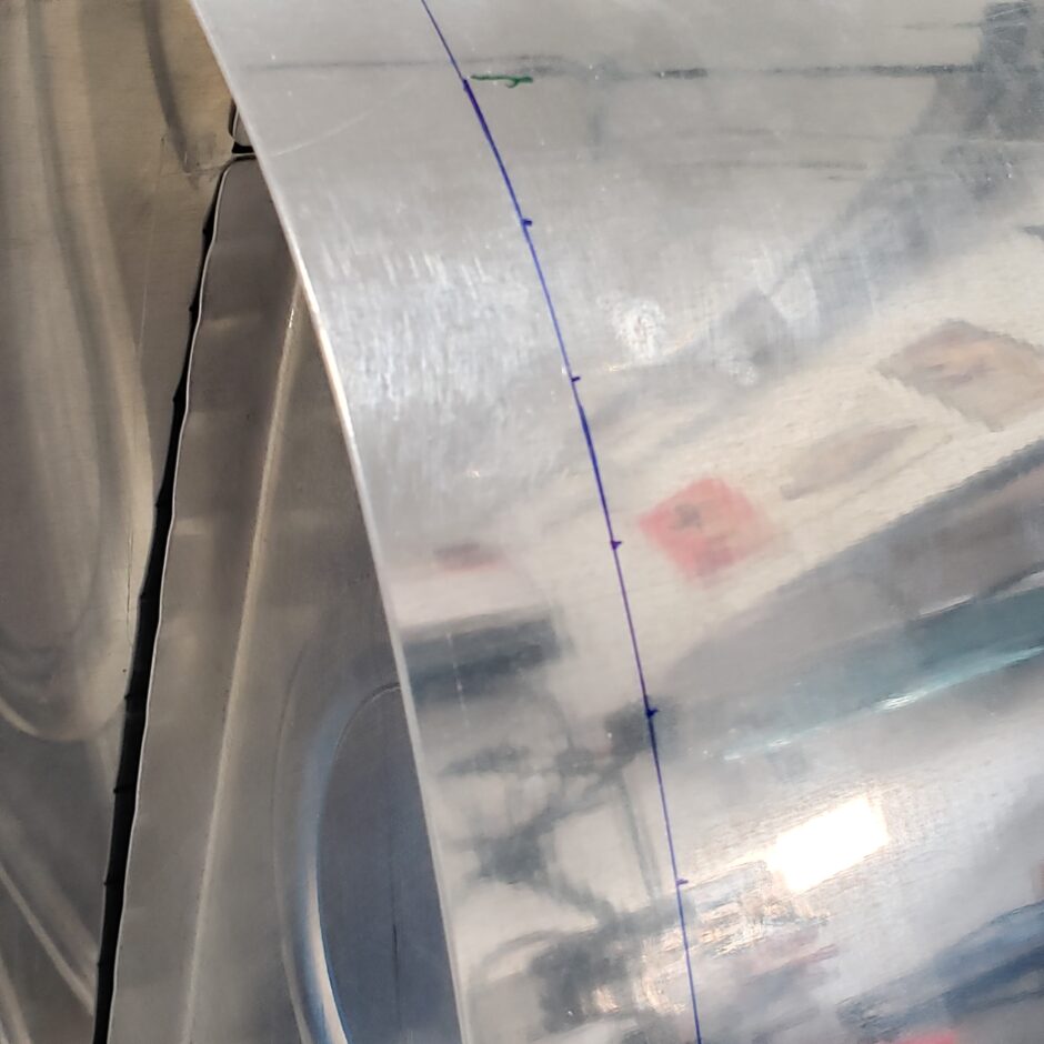
Today I’m ready to start working on figuring out the left hand fuel tank skin rivet pattern layouts. I began with the easiest point of the skin layout, which was the rivets for the inboard tank end rib. This was easy to establish where to begin and end, as well as all points in between. As you can see in the picture below, I started by mostly eyeballing where the rib notches and flutes are. Obviously the rivets need to land between these on the flats. The arrows below indicate the tabs at the leading edge where the rivet line begins.

According to the plans, the tank end ribs have a 3/4 inch rivet spacing.
When starting the layout for the inner ribs, I took a rib from other fuel tank to use in helping me to figure out rivet spacing for the inner ribs (1 inch spacing). Even though the spacing is shown on the plans as all being equal for either the end ribs (3/4 inch) or for the inner ribs at 1-inch, take that with a grain of salt. Which I why I’m using the ribs, to visually identify where the flanges are and to locate the rivet hole as best as I can on the center of the flange, and not where the flange has been fluted.
For the most part the spacing is as shown on the plans but not perfect.
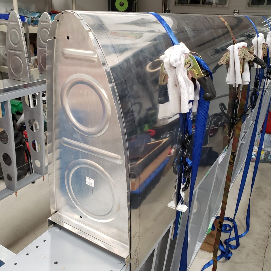
As you can see in this picture below, I have the end rib already marked for where to drill the rivet holes (blue line), and you can easily see that the spacing isn’t an even 3/4 inch. I found that the spacing differs more so near the leading edge then settles down to the required dimensions after the first few inches.
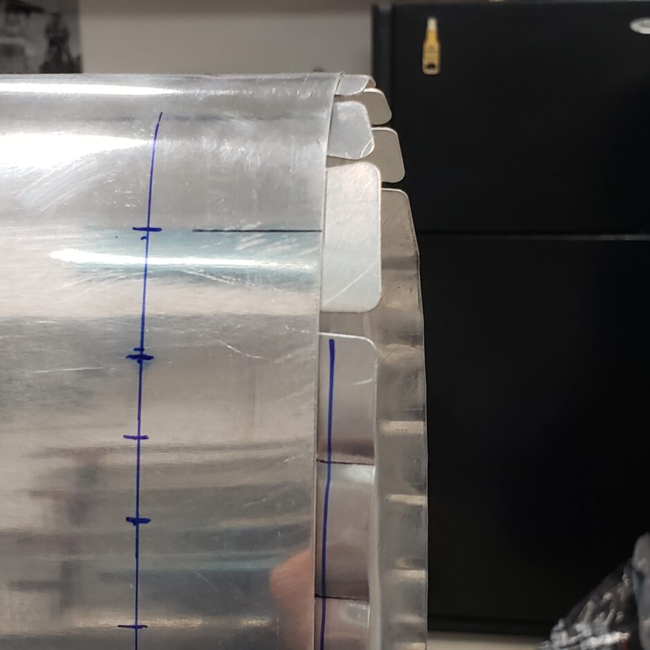
Also in this picture below, I have one of the inner ribs from the other tank that I placed in the end, to help me locate the actual rivet spacing on the inner ribs. Another item to note that may help you is that all the first rivets (closest to the leading edge are all in alignment (see the black and the blue lines). That will give you a good starting point! I used this, when measured up from the end of the spar flange. Then I marked the rivet spacing down from there, again, all the rivets on the lower end of the line, are also all in alignment.
Below I have the rivet spacing marked out for the inner rib (purple) and as you can see, not all the dimensions are evenly spaced at 1-inch as per the plans.
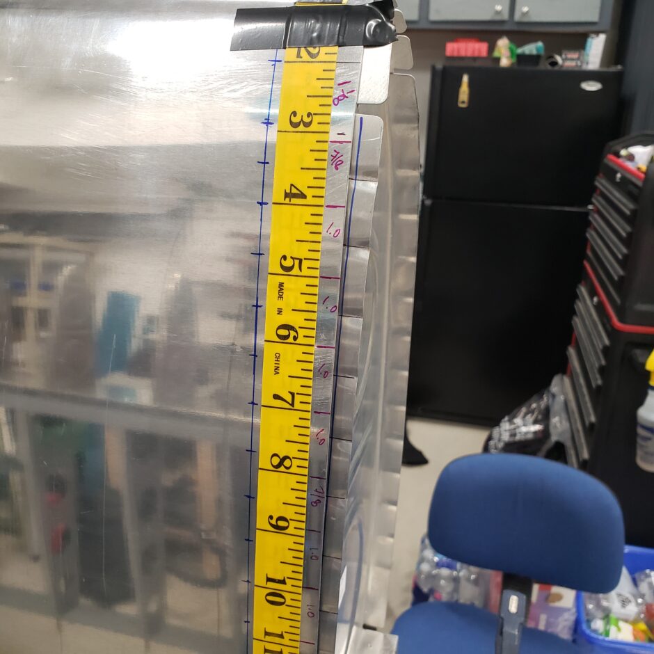
With the actual rivet spacing now determined for both the inner and end ribs, I am now able to layout the rest of the rivet lines.
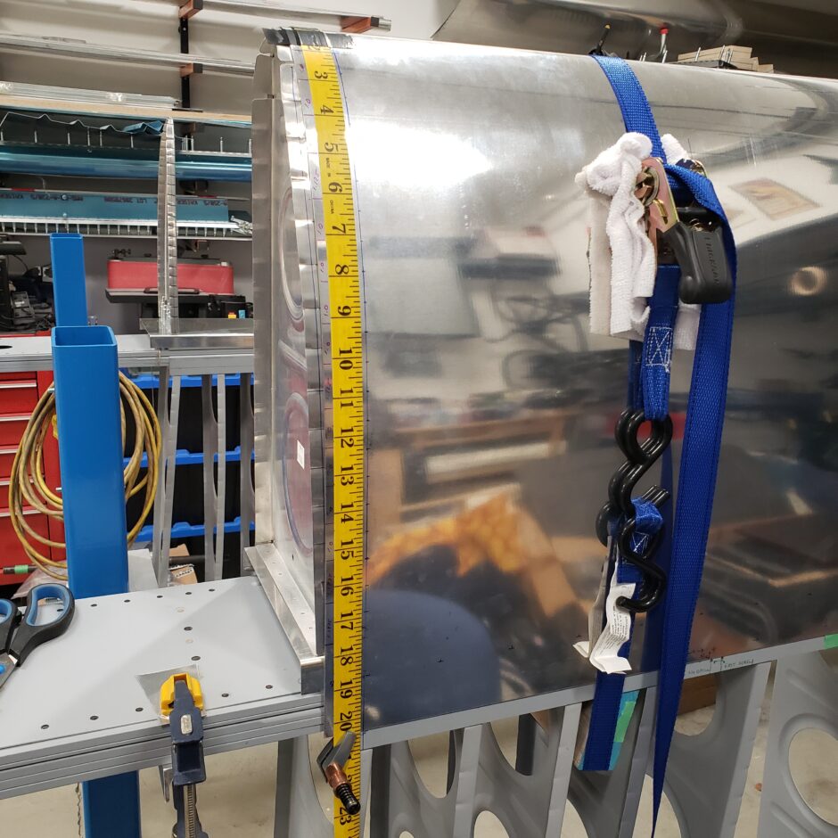
Lower rib rivets – measured up from the edge of the spar flange (3.410 inch) – same all the way across for all inner and end ribs.
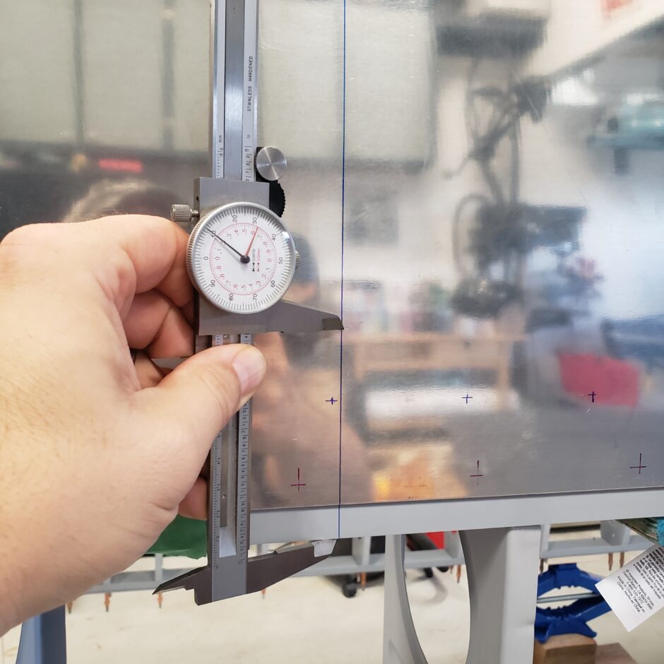
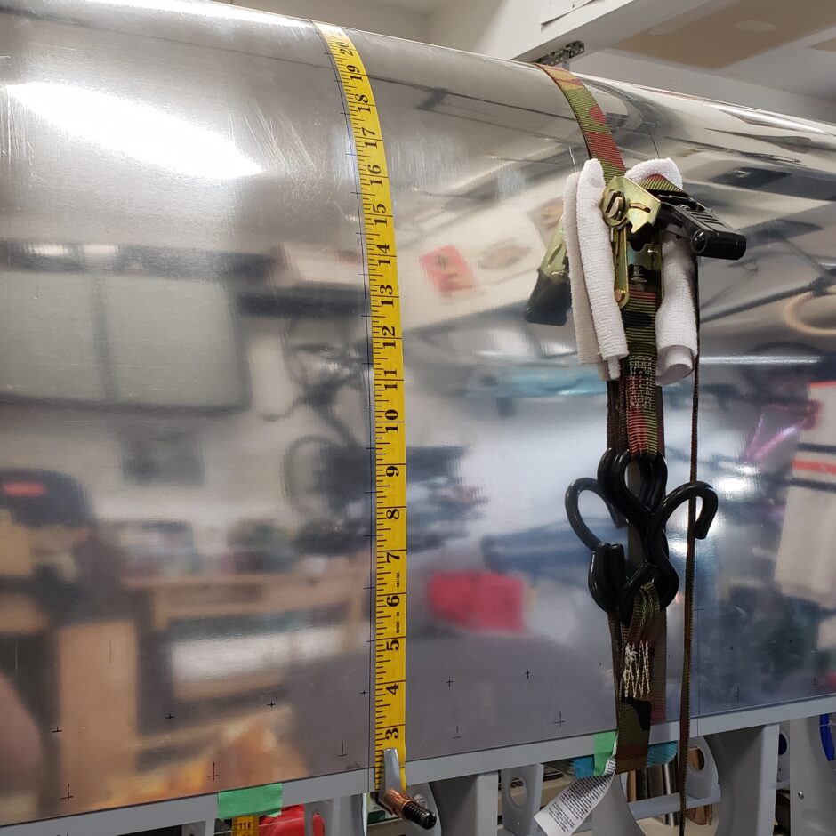
With the lower end of the rivet line identified (as in the picture above) I was then able to set the measuring tape on that mark and working up from there, locate the upper most rivet. Then I would work my way back down marking the proper spacing as required. If the last dimension to the lowest rivet fell in place, I marked the rivet line correctly. If it didn’t, I went back and found my error in the layout spacing. This worked as a good way to double check my layout work as I went.
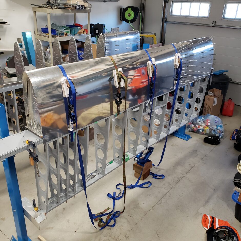
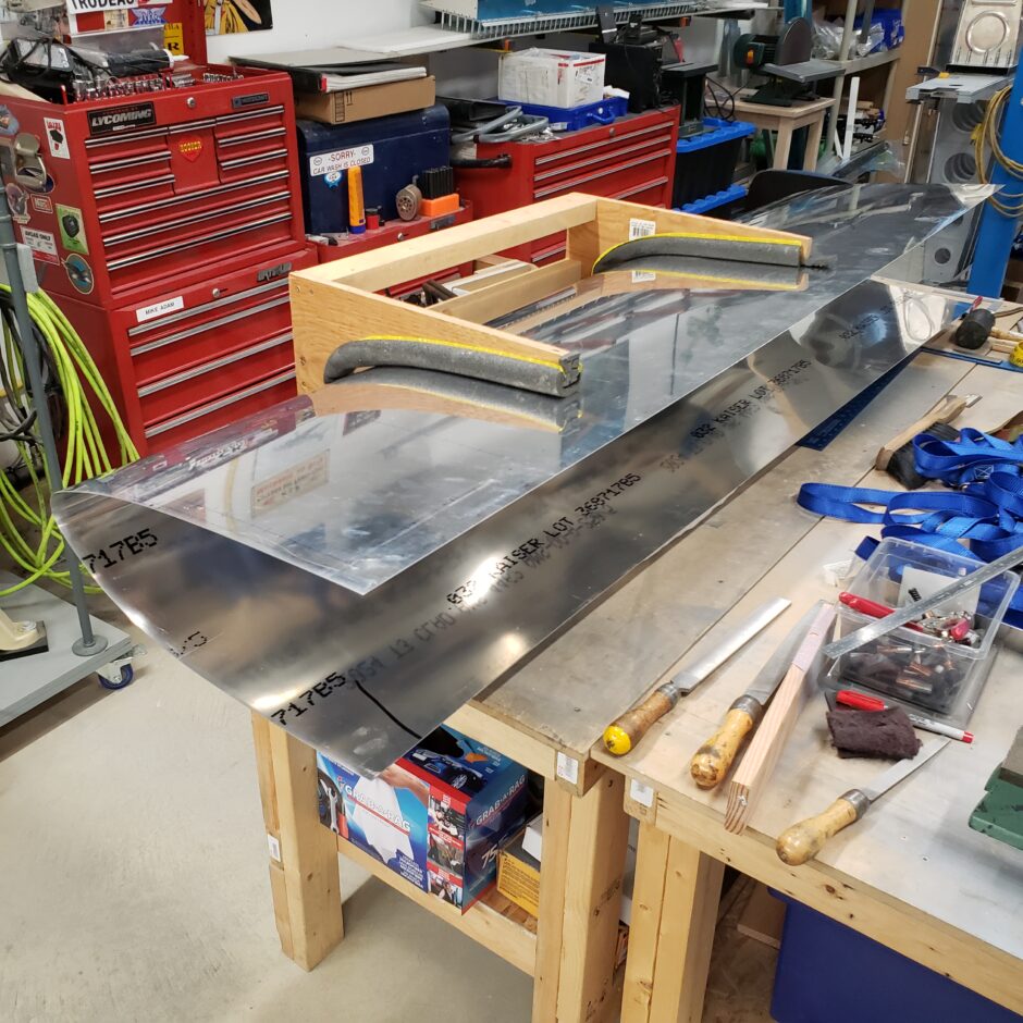
Here the skin has all the rivet lines laid out and I’m ready to take the tank skin off and transfer it to the bench.
Once on the bench, the next job was to centerpunch all the holes.
While the skin was off, I also took this opportunity to get the proper dimensions for the screw locations that will eventually fasten the tank skin to the main spar. This screw line has been previously marked (in green) as per the plans. The blue line is the tank and wing skin butt joint line.
Once again, I measured this dimension up from the end of the spar flange. This is a good known dimension, as when the skin is in place, the end may be longer (or shorter) than the butt joint line, and will make it difficult to know where exactly the green line is. By measuring from the end of the spar flange, I know that all my screws will be located the same at 0.900-inch.
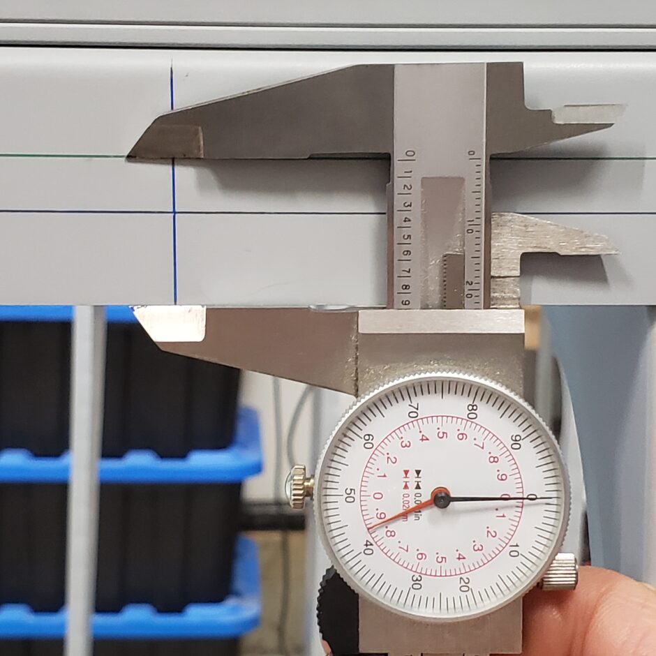
Again, just to double check, using the other side of the caliper, when rested against the spar flange, the indicator again shows directly on the green line. I can now use this to check where this dimension falls on the inside of the spar flange, where the nutplate needs to be located.
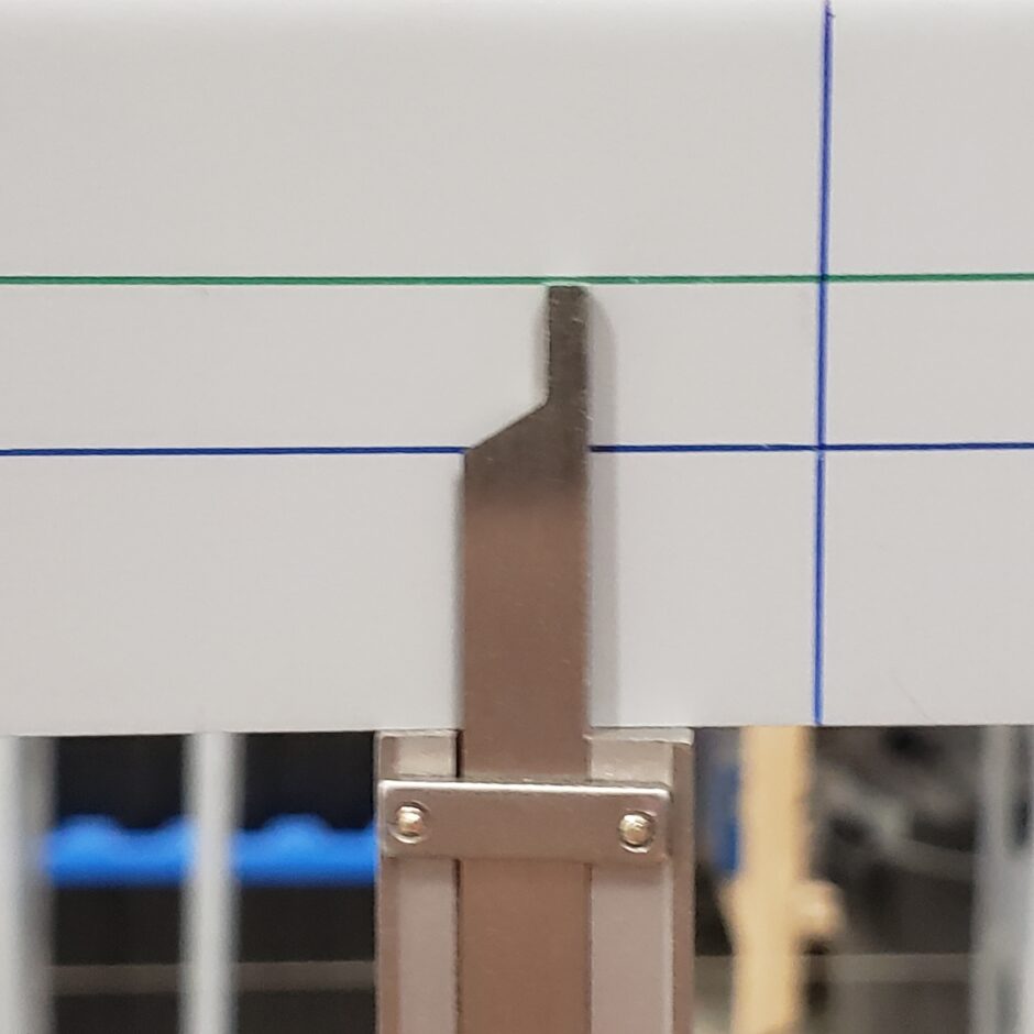
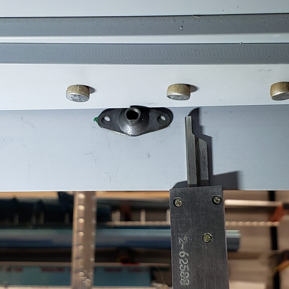
This is a very tight spot for the location of the first nutplate. Using the caliper, I can verify that I’m able to fit the nutplate in place. The green dot is the location of one of the nutplate rivet holes that I transcribed on. The goo to the right of the caliper is some seal-lube I used to help hold the nutplate in place while played with the measurements.
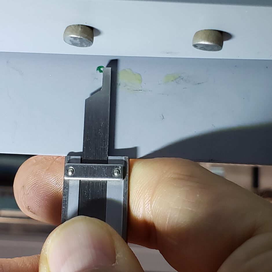
As shown in this picture below, this is a VERY tight spot for locating the most inboard nutplate. This is one area you definitely want to double check before you drill!
That’s all for today folks! Please comment, I love to hear from my readers. Thanks again for coming along for this ride, you make my work worthwhile.
Leave a Reply