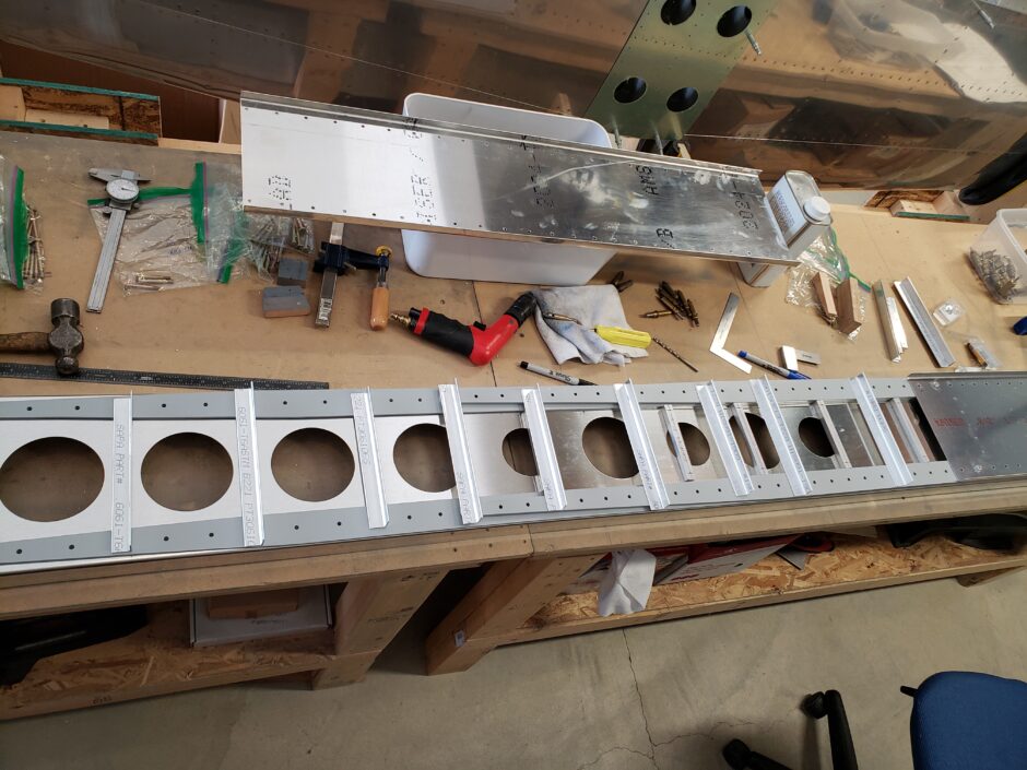
Today I’m working on locating and drilling the wing rib attach angles (and a few spar stiffener angles). In the picture below you can see that I have already cut the angles and generally have them in the proper locations.
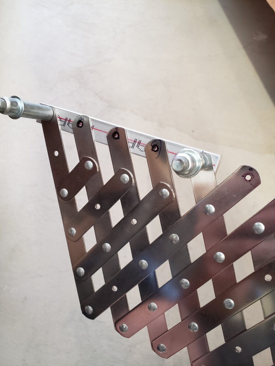
The rivet layout for these angles is straight forward. I marked the centerline, drilled a pilot hole on each end and then used the rivet spacer fan to set equal spacing along each angle.
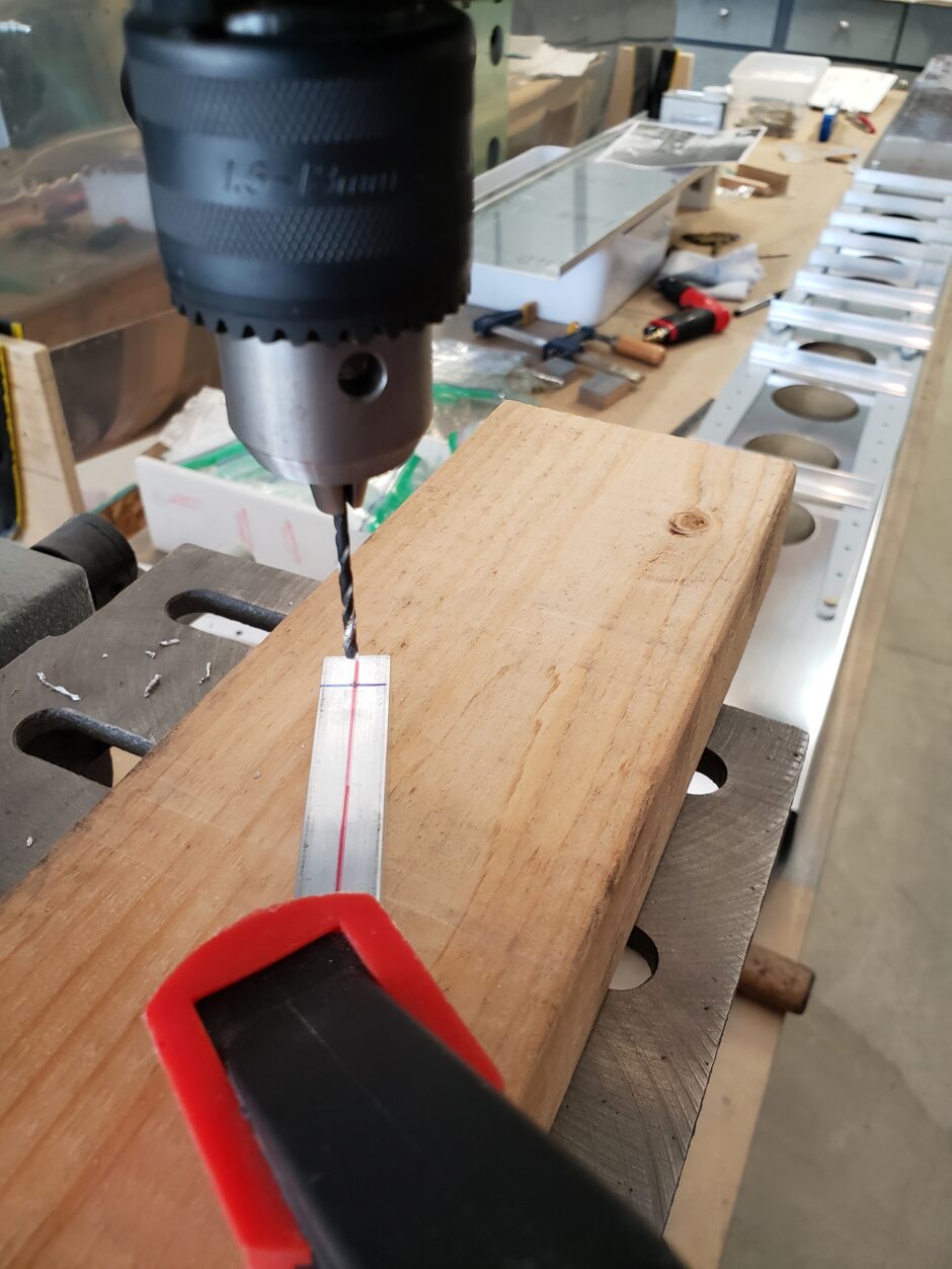
Where possible, I like to drill with using the drill press. This is mostly an attempt to get the straightest holes possible.
Spar Web Spacer Blocks
The following images will provide a bit more details about the spacing I used for my spar web spacer blocks.
In the image below you can see the first additional spacer block that I’m putting in below the spar web extension doubler area.
Another important mod to take note of is also the TR-W-006B3 doubler. This is an addition on the F1 Rocket plans, that isn’t on the HRII Sport Wing plans. This doubler joins both of the forward spar web doublers together.
The first additional spar web spacer block (I call it R1) sits just outboard of this doubler.
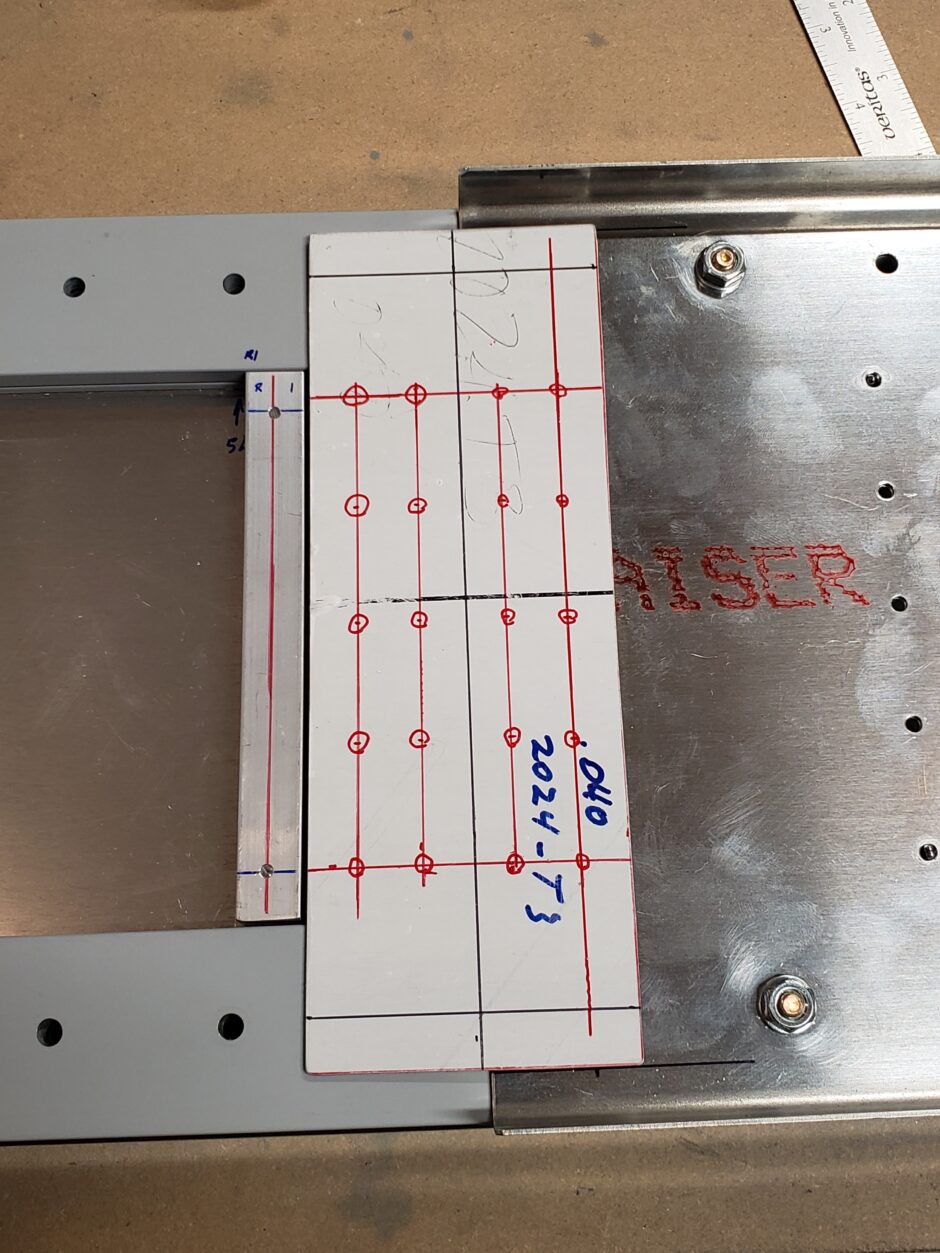
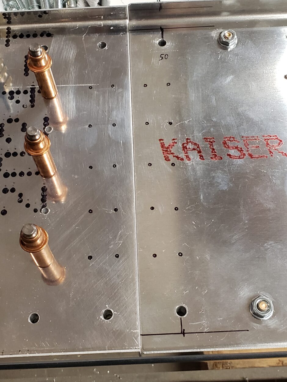
The picture below shows the rivet layout details of the doubler.
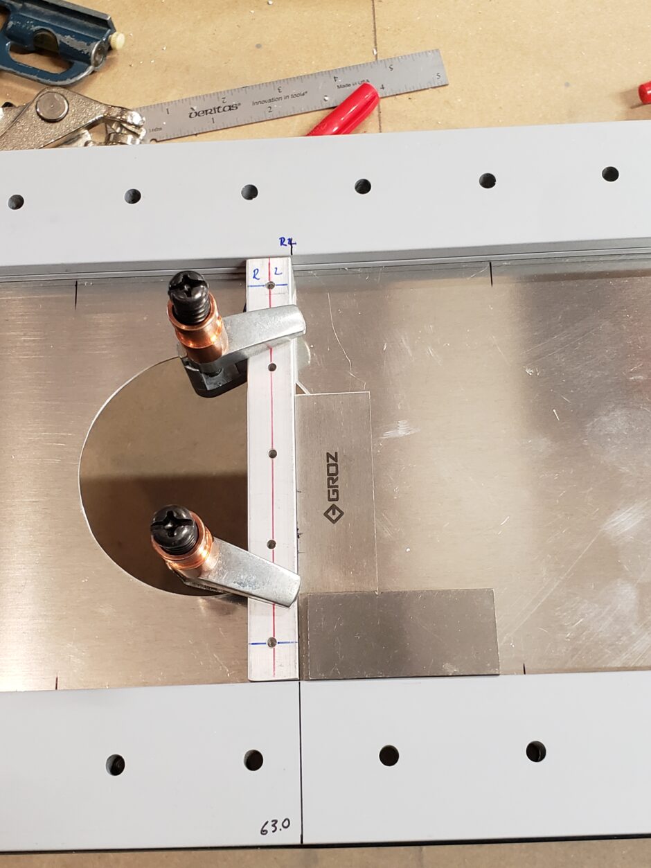
Below is the R2 spacer block, located at 63.0 inches. One thing to note on this spacer block is that it overlaps the RV-4 factory drilled lightening hole. There is really no way to avoid this, so you just have to work with it.
The way I choose to deal with this is that I will install countersunk rivets in the 2 holes that are close to the edge of the hole, on the aft side, as there will not be enough room for the standard universal head rivet. All the spacer block rivets are installed with the manufactured heads to the forward side of the spar and the shop heads on the aft side. For these countersunk rivets, I had to install these rivets in the opposite direction, to make them work.
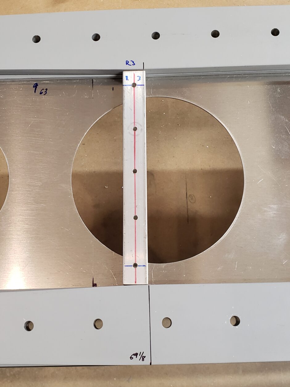
In the image below shows the location of R3 at 69 1/8 inch. Again, this spacer block in spanning a lightening hole. I was happy with the edge distance provided by this location for the outer holes. I decided to move this outboard a bit to be able to get better edge distance (shown further below).
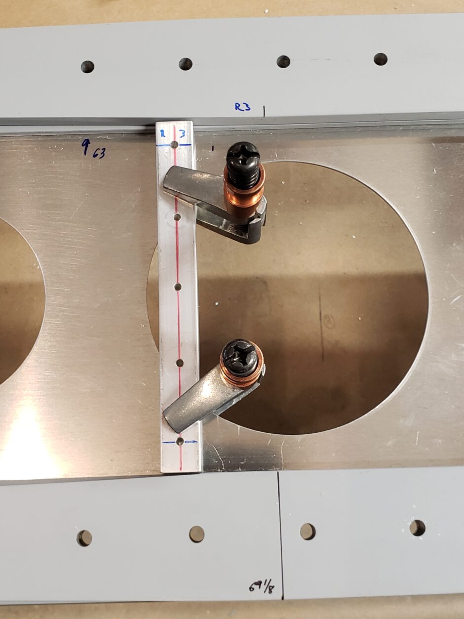
In the following picture, you can see how I moved the spacer bar out about an inch. As you can see the edge distance is much better. Again, this spacer block will also need to have 2 countersunk rivets where the rivet heads would interfere with the edge of the hole.
The next two pictures are taken from the other side of the spar, which shows how the lightening hole interferes with the rivet hole locations, which is why I chose to make these installed with flat heads.
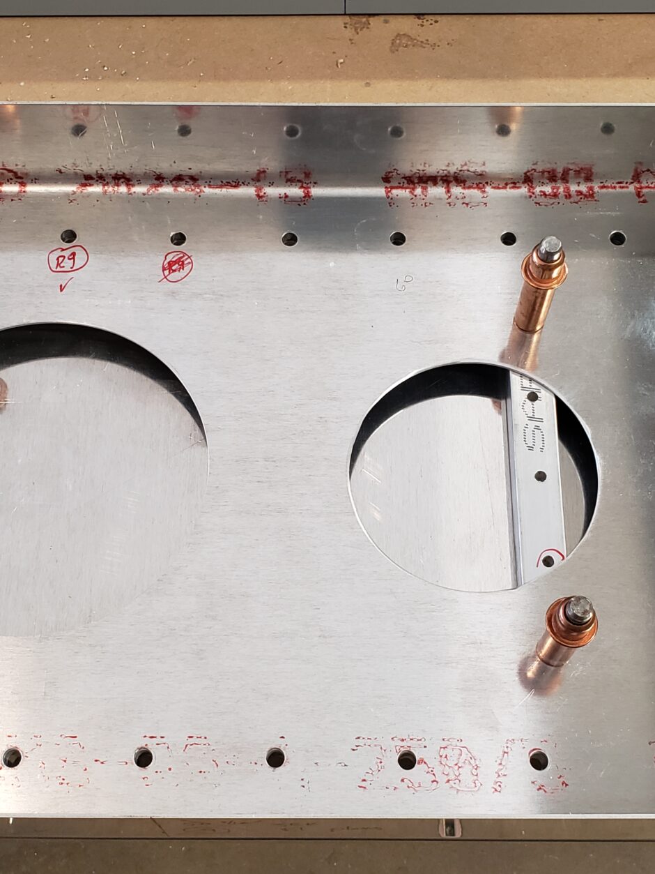
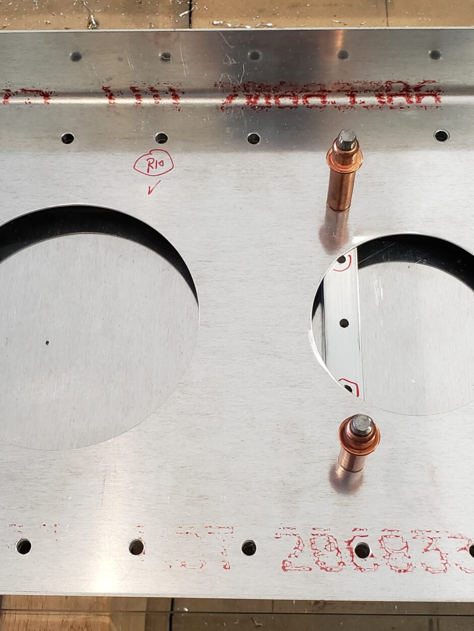
Below is R4, located at 74 1/8 inch. Again, dealing with the lightening hole, and again, I’ll be using countersunk rivets in the area of the hole edge.
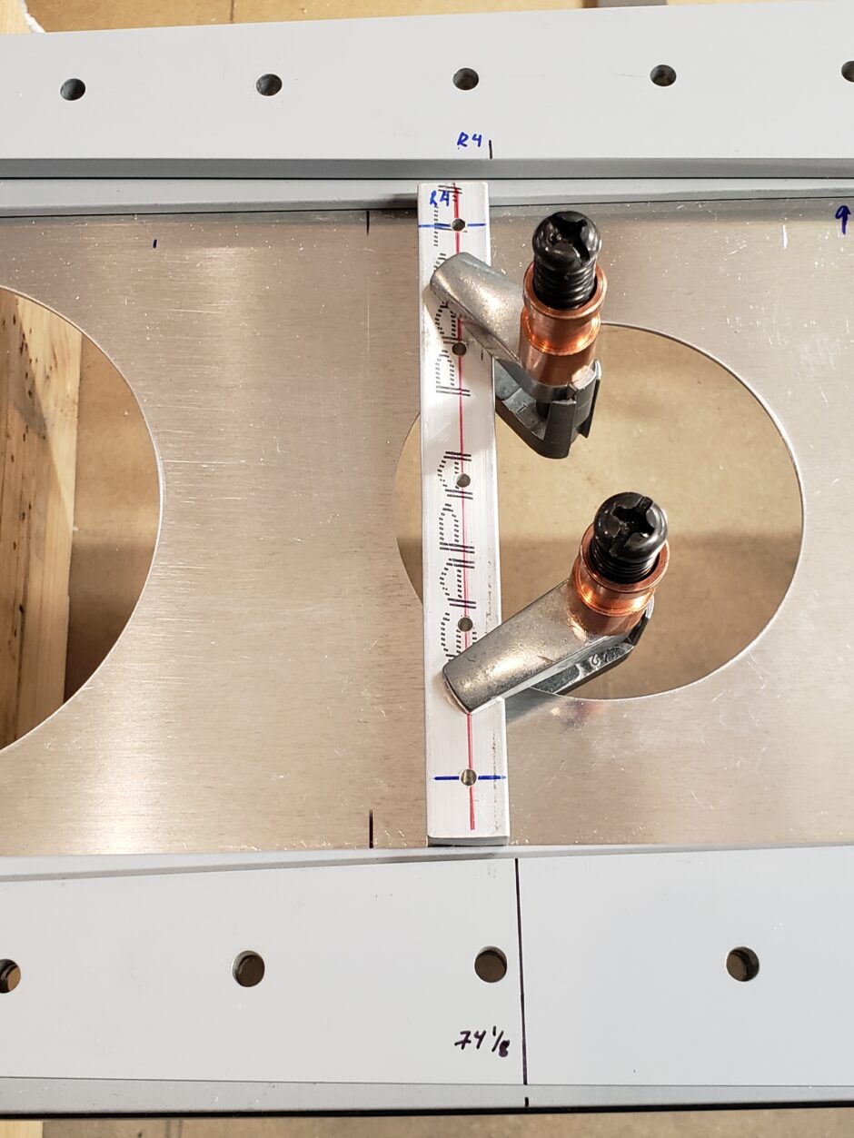
Spacer block R5 below, located at 81 1/4 inch. No edge distance issues here.
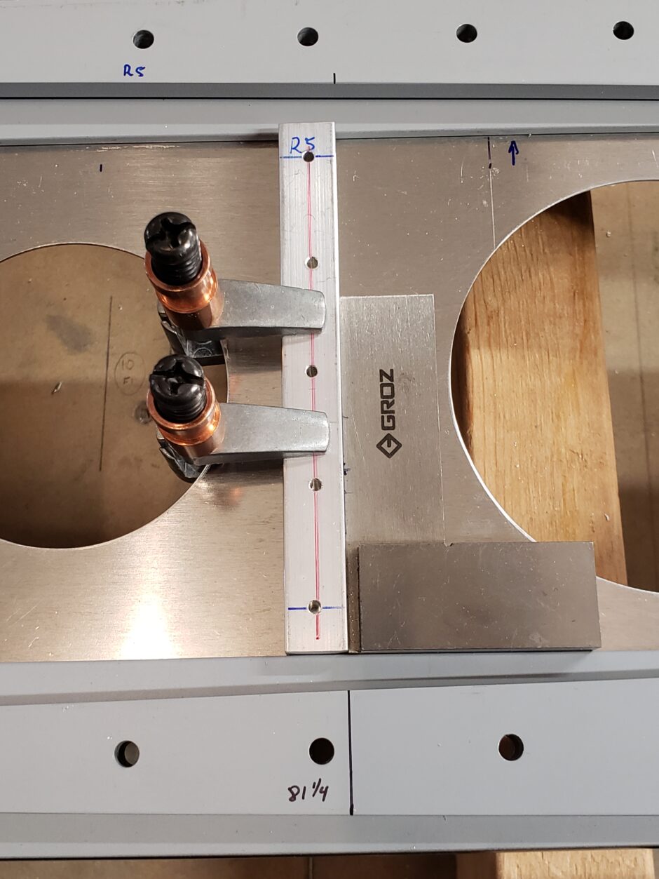
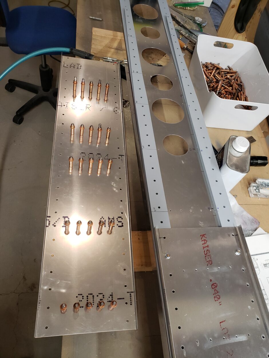
With the spacer blocked properly located, they were drilled to the main spar web. Once drilled to the spar web, I put the forward spar web doubler extension back onto the spar, and then back drilled all the spacer block holes. This can be seen in the image below.
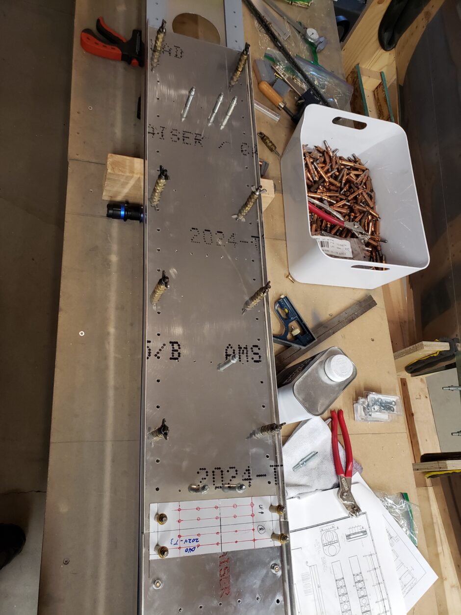
The image below is the back side of the forward spar web extension which shows the spacer blocks located and drilled to the extension doubler.
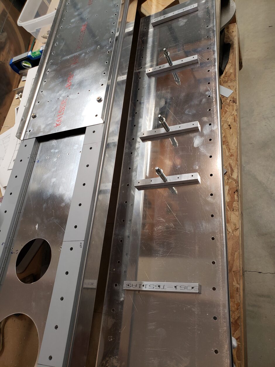
Below, the spacer blocks have been drilled to the final #30 size.
Please comment. I love to hear from my readers. Thanks again for coming along for this ride, you make my work worthwhile.
Leave a Reply