Today I ventured into getting the rear spar W-407D doubler drilled to the spar along with the W-407B and W-407C flanges. This took me quite a while to figure out. At first, as you will see below, ribs just weren’t lining up with their appropriate locations. It took a little bit of work before I was confident enough to drill any of these parts.
A word of warning here…As per Vince’s comments there are not a lot of dimensions shown for the rear spar. Following Vince’s guidance, I marked the main spar at 15 11/16 inches from the root end (see drawing # 109) and this was a good starting point.
I then set the rear spar next to the main spar and started transferring rib location dimensions from the main spar to the rear spar.
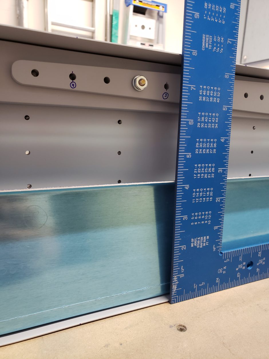
Another way to verify that you have the rear spar properly located is to line up the outboard ends of both spars because the ends are located at the same wing station.

In an attempt to keep things simple, you will notice here and in much of my discussions moving forward that I have numbered the wing ribs (1 – 14) and they are numbered as # 1 being the inboard most rib to #14 which is the tip rib.
I did this partly because the dimensions for wing stations (rib locations) given in the HRII drawings are different than those given in the F1 plans. By numbering the ribs 1-14 I found it to be much easier to keep track of the rib locations.

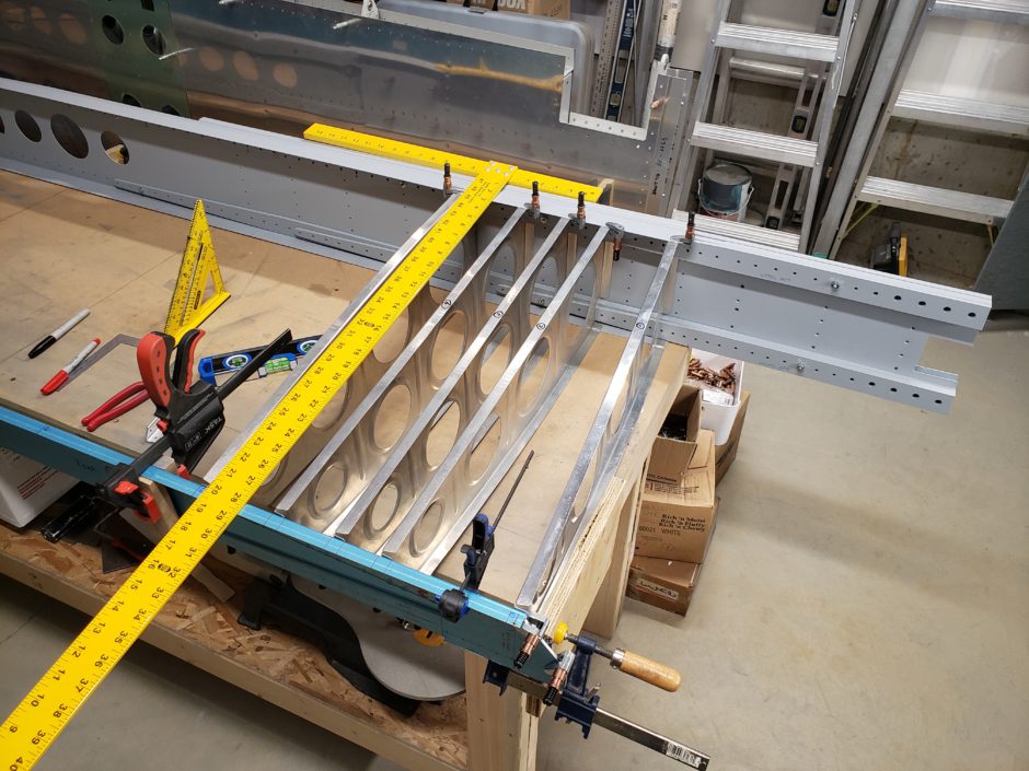
At this point, I’m only concerned with the location of the first 5 ribs as they are the ones that align with the W-407 flanges and doubler. As you can see in the picture below, I clamped up this area and ensured that the ribs were all perpendicular to the spar. I was then able to confirm the measurements and transfer these lines to locate the ribs on the rear spar.
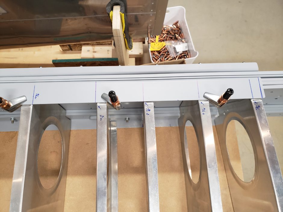
Here is a closer image of some of the locating lines and measurements.
As mentioned above, it took a while before I was comfortable with the measurements and layout before I drilled any of these holes. If you look closely at the next few pictures, you will see that some of the ribs were not lining up with the locations specified by the plans. The W-407 doubler and flanges below are laid out as per the HRII drawings, in particular, using the rivet spacing detailed on Drawing 112.
W-407D Doubler Notes
When counting rivet holes, on the W-407D doubler, there are 5 rivet locations with the most inboard being the location of the # 1 rib (inboard) rib.
I also want to add a note here that the HRII plans are not accurate in the rivet spacing and edge distance for the W-407D doubler. As seen in the image below the plans show the spacing to be 0.813 with 6 spaces. This part also has 1/4-inch edge distance.
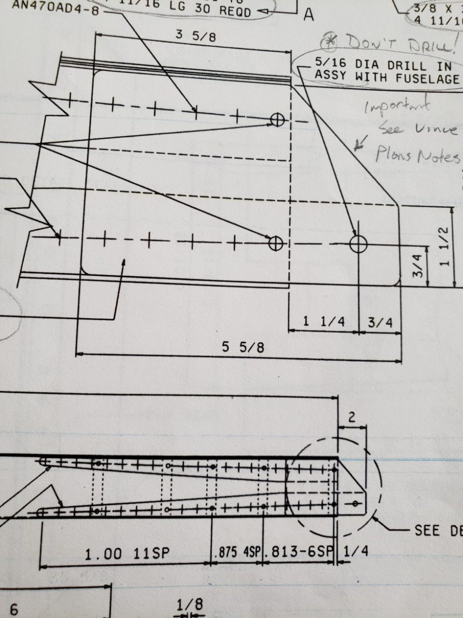
On the W-407D doubler there are 5 rivet locations – two of which are on the ends which require the 1/4-inch edge distance. Add the 0.813 spacing to 4 spaces (5 rivet locations) plus the 0.500 of edge distance (2 edges) and you get a total length of 3.752 inch. Whereas the W-407D part length (riveted portion only) is 3 5/8 (3.625″) inch.
Rear Spar Flange and Doubler Layout
Moving outboard, rivet hole # 7 (on the upper flange) as per the HRII plans is the location of rib # 2. In the image below, you can see that location is 1 hole too far inboard.
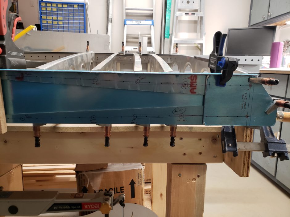
Here is a closer look at the location of rib # 2 and as you can see, the “No Drill” location marked for the # 2 rib is one hole too far inboard. Where as, with the # 3 rib location to the left, it is lined up.
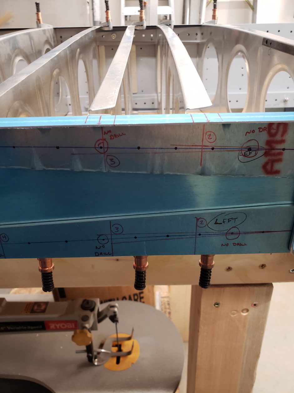
In the image below, you can see that both locations for rib # 3 and rib # 4 are both in alignment.
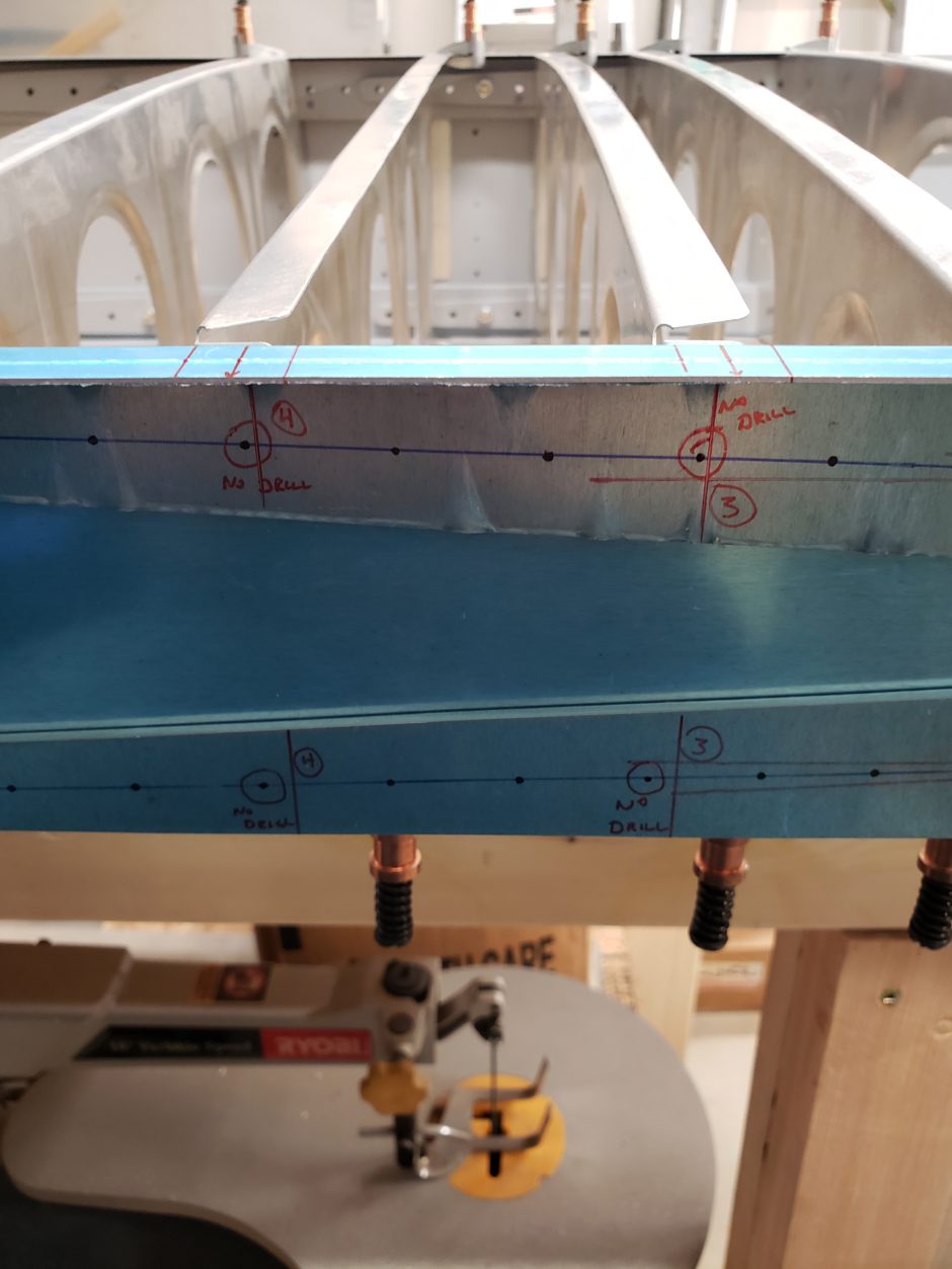
In the image below, the rib alignment as per the HRII plans is one rivet hole too far outboard.
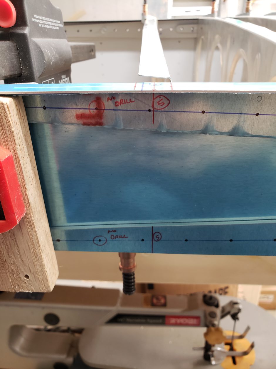
At this point, I wasn’t happy with how things are lining up so I decided to quit for the night. Time to go back and review the plans.
Please comment. I love to hear from my readers. Thanks again for coming along for this ride, you make my work worthwhile.
I hope you figured out to ignore the HRII plans and use the TR plans. I’ve been going through the exact same struggle.
You really need to look at all the plans (TR / HRII and RV-4) to fully understand each step of the build process and to see the big picture of what you’re trying to do before you commit to drilling anything. The struggle is real.