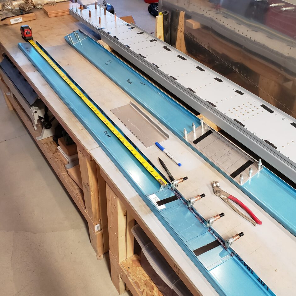
Today, the task I’m setting out to get the rear wing spars ready for riveting. In the image below, I’m working to locate the TR-W-007F rear spar – aileron attach doubler which is riveted to the rear side of the rear spars. This is a bit tricky as the plans don’t give you much in the way to work with for dimension, and the dimensions they do give, I need to be mindful that my double plate is longer than specified in the plans.
Recall that in modifying the RV-4 wing into the F1 Sport Wing, there are a few improvements made, one of which is this doubler. In the RV-4 plans, the W-407F doubler is only 5 1/2-inches in length. In the HRII plans, the W-7F doubler has been increased in size to 9-inches. And finally, for the F1 the TR-W-007F doubler has been further increased to 11-inches. So again, be mindful of the spanwise measurements shown being measured from the end of the doubler!!
Inboard Aileron Hinge Doubler (TR-W-007F)
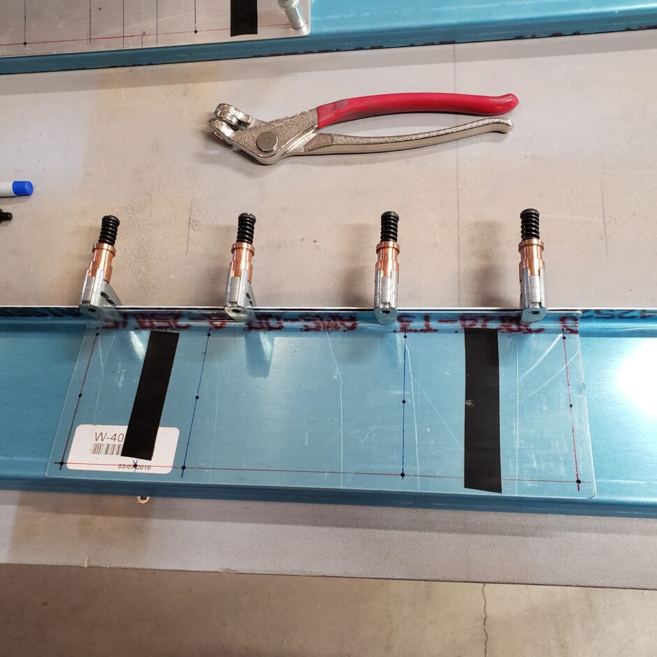
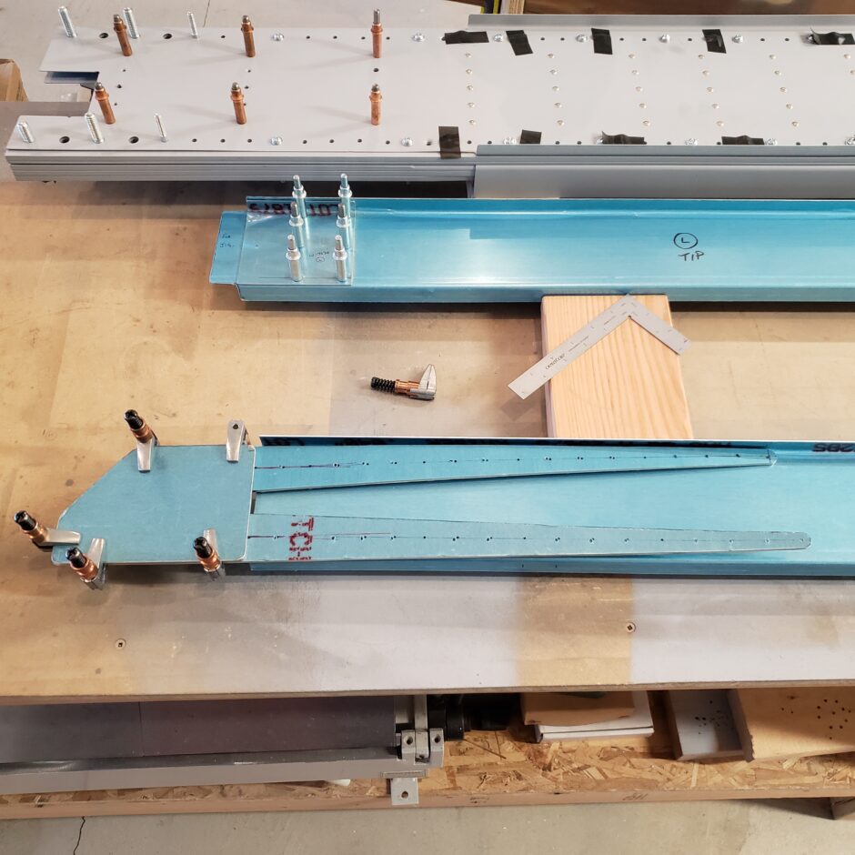
In the image below, I located these doublers as best I could with the lack of hard dimensions shown. A big key here to help determine these measurements is to use the #9 and #10 wing ribs aid in locating. In the picture below, you’ll see that I placed a strip of electrical tape in the general area of these wing ribs to make sure I don’t drill anything there.
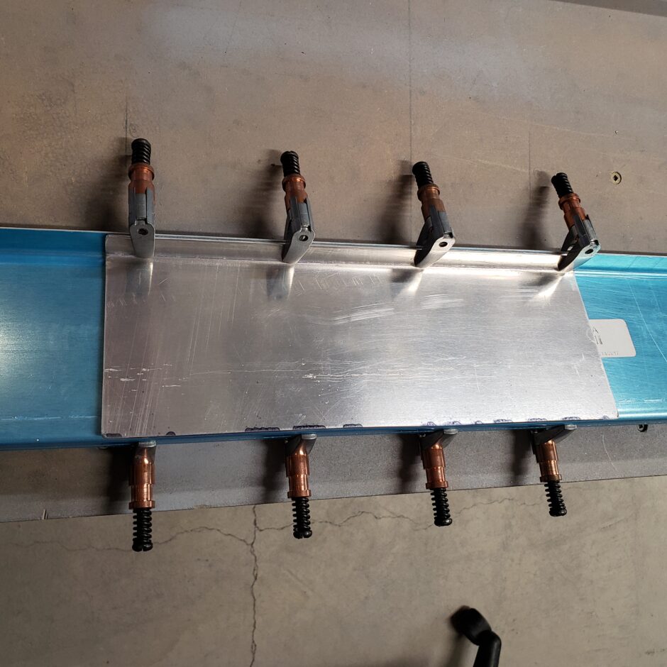
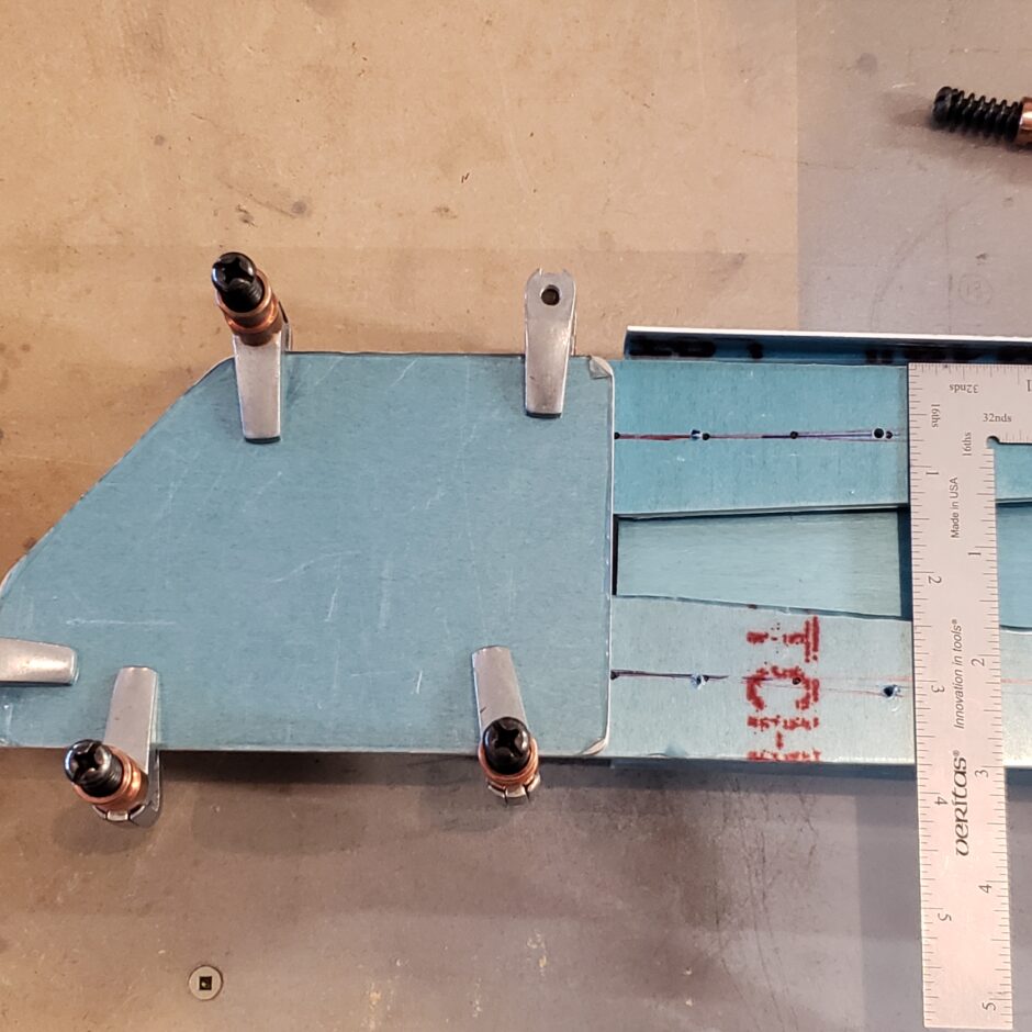
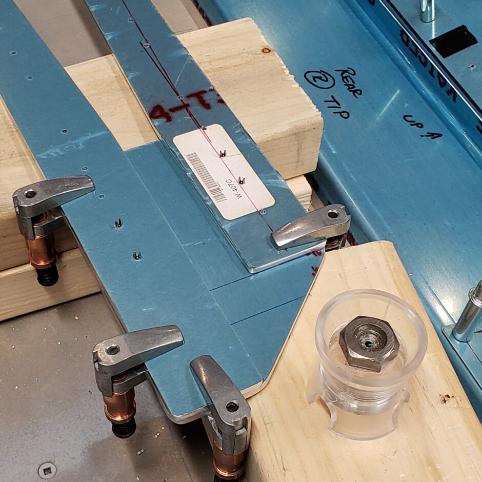
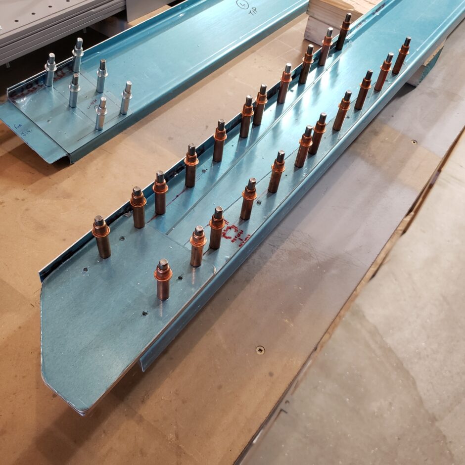
Here is a closer picture to show the details of the TR-W-007F doubler.
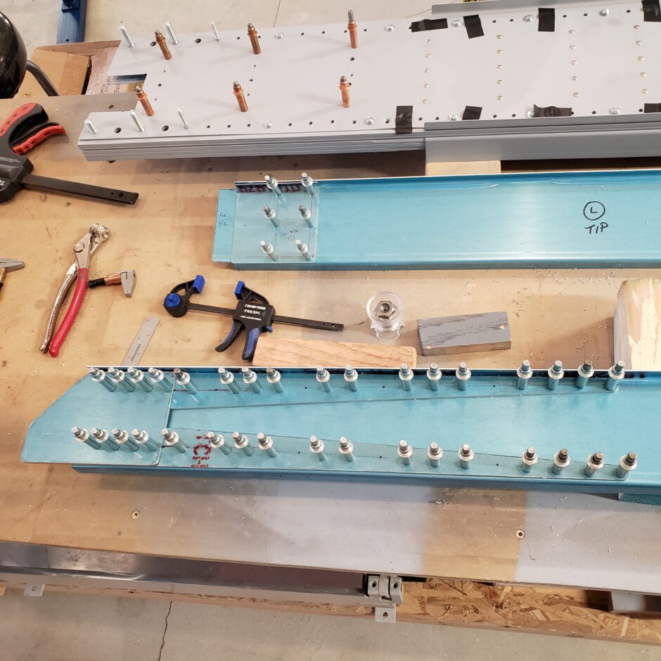
In addition to the TR-W-007F doubler, and this being a known week area of the design, several F1 builders have added an additional 0.063 doubler on the forward side of the rear spar to match that of the TR-W-007F doubler. I chose to do the same. Shown in the image below is the additional doubler being located in relation to the TR-W-007F part.
I’m not drilling this yet. I’m going to move on for now and come back a bit later to make sure these doublers are located properly.
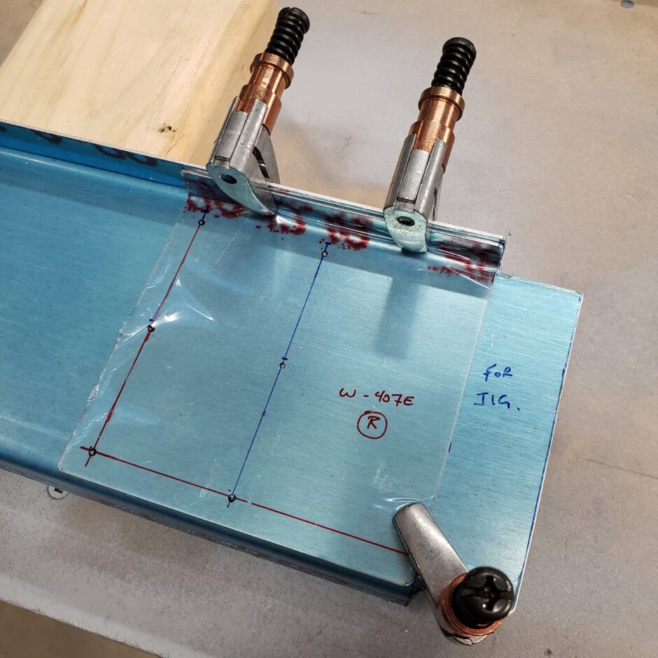
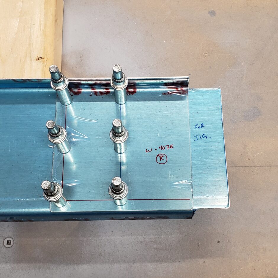
Outboard aileron hinge doubler (TR-W-007E)
I’m moving on to locating the W-407E outboard aileron hinge doublers. These are pretty straightforward and are clearly shown in the plans.
Rear Spar Wing Attach Fitting
Moving on the wing root end of the rear spar, I began by drilling #40 pilot holes into both the W-407B and W-407C spar flange strips. Again, in the picture below, note the areas where I added a few pieces of electrical tape to identify where the wing ribs are located, so I don’t accidentially drill unwanted holes.
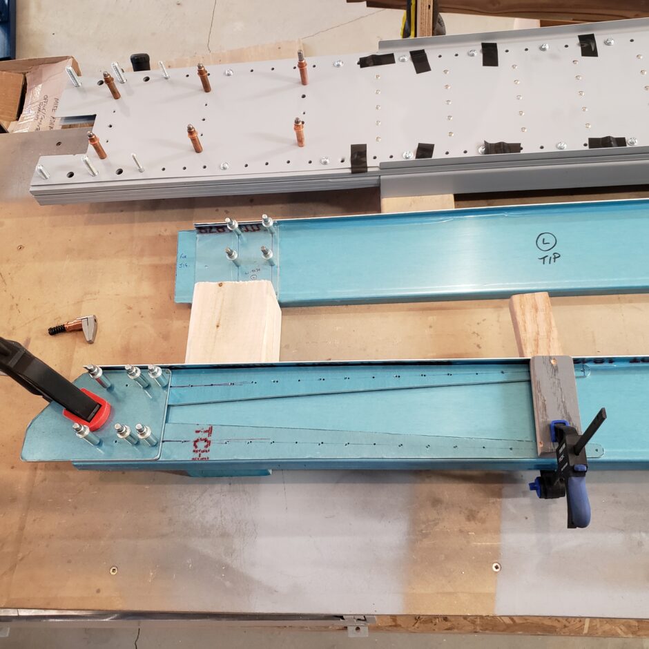
With both of the W-407B/C spar flange strips drilled, the next step was to get the W-407D plate clamped and aligned with the spar flange strips, and eventually aligned with the rear wing spar.
One key thing to getting these spar flange strips properly aligned with the W-407D plate is to ensure the outer dimension of the entire assembly which is 3 3/4-inch. Once getting this dimension set, I had a good place to start for getting the assembly located on the spar web.
However, as it’s being held together with my little helpers (cleco clamps) this makes it really difficult to get the assembly aligned with the spar. So I match drilled the spar flange strips to the W-407D plate so it can be clecoed.
Now with the spar flange strips and W-407D plate together as an assembly, it’s much easier for me to locate this assembly on the spar. Once it was located, I clamped it in place so I could begin match drilling all the pilot holes. This process worked really well and gave me a good bit of accuracy.
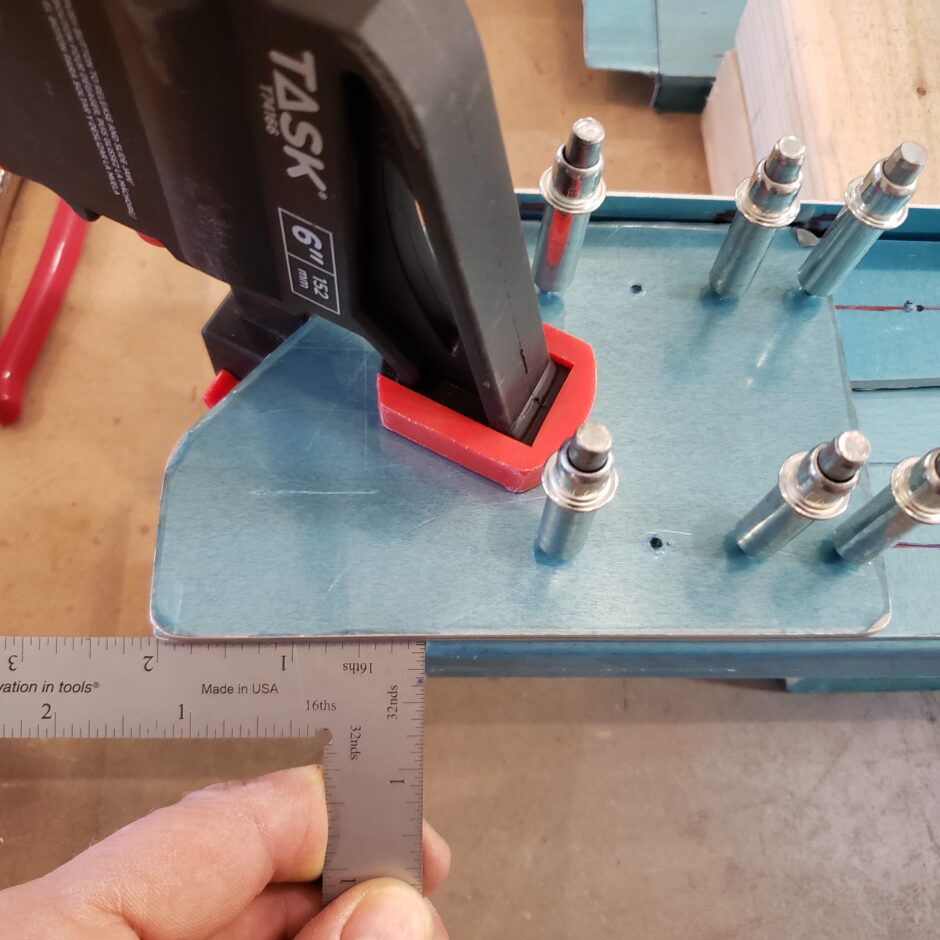
Again, before you drill anything, double check all the dimensions. In particular the amount of overhang of the spar flange/plate assembly inboard of the spar which is 2-inches!!
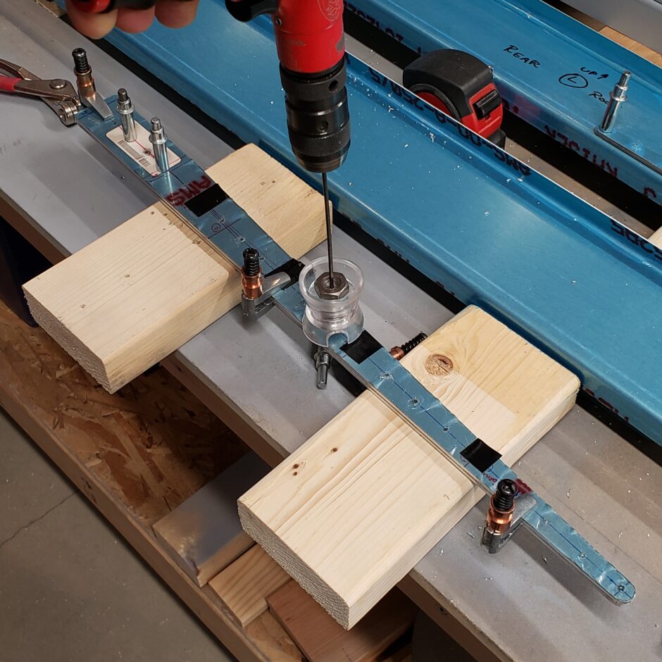
Below are a few pictures of the match drilling.
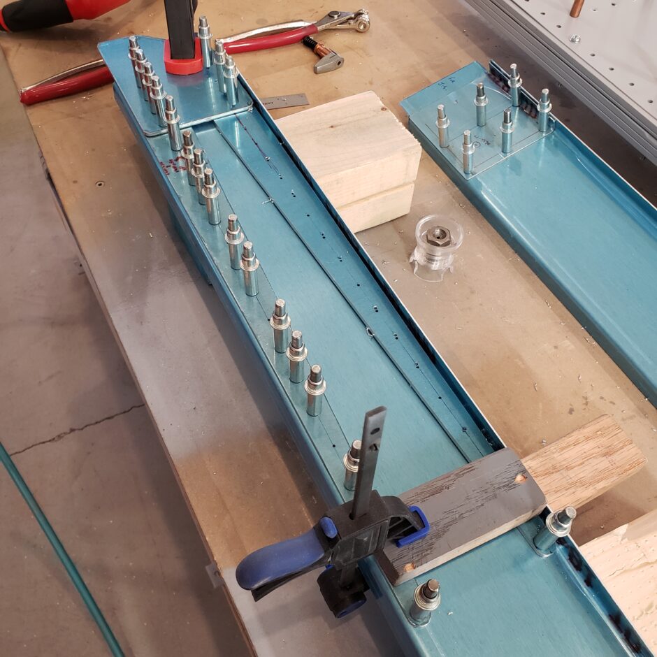
Once all the pilot holes were drilled, I final drilled them to #30.
Please comment. I love to hear from my readers. Thanks again for coming along for this ride, you make my work worthwhile.
Leave a Reply