In the last post we left off with getting the outboard ribs located (# 12 and 13) as shown below.
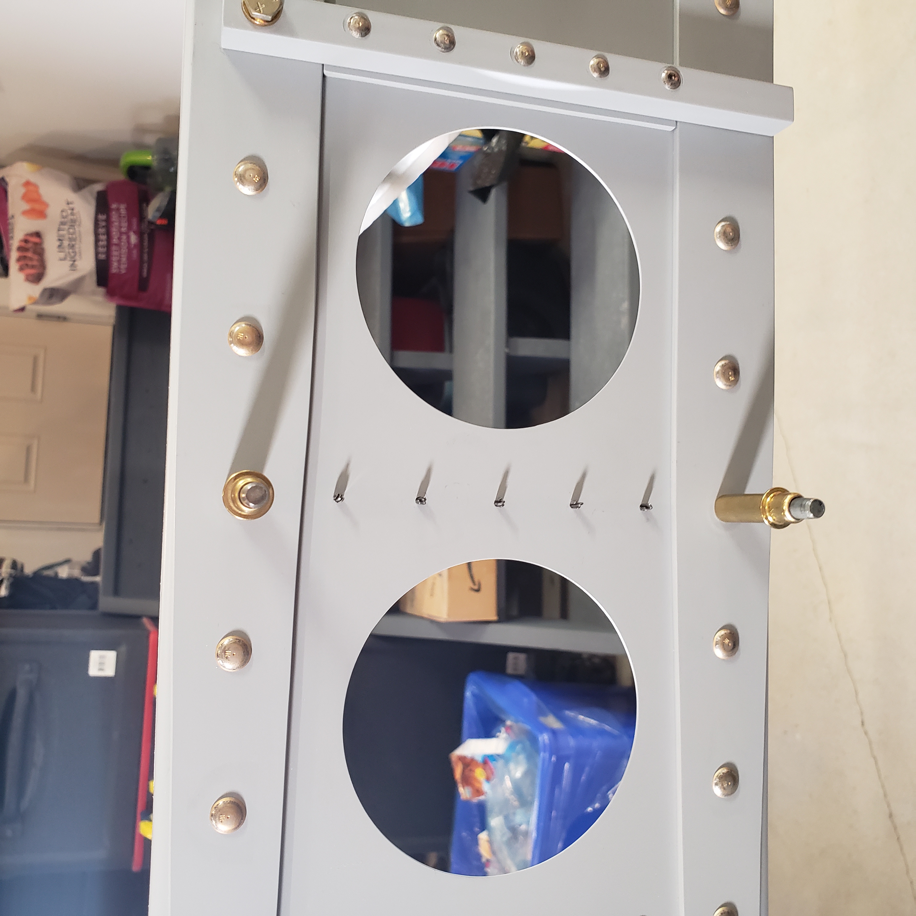
Then I got the leading edge rib attach angle clamped in place.
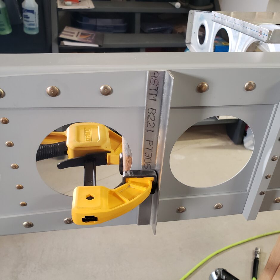
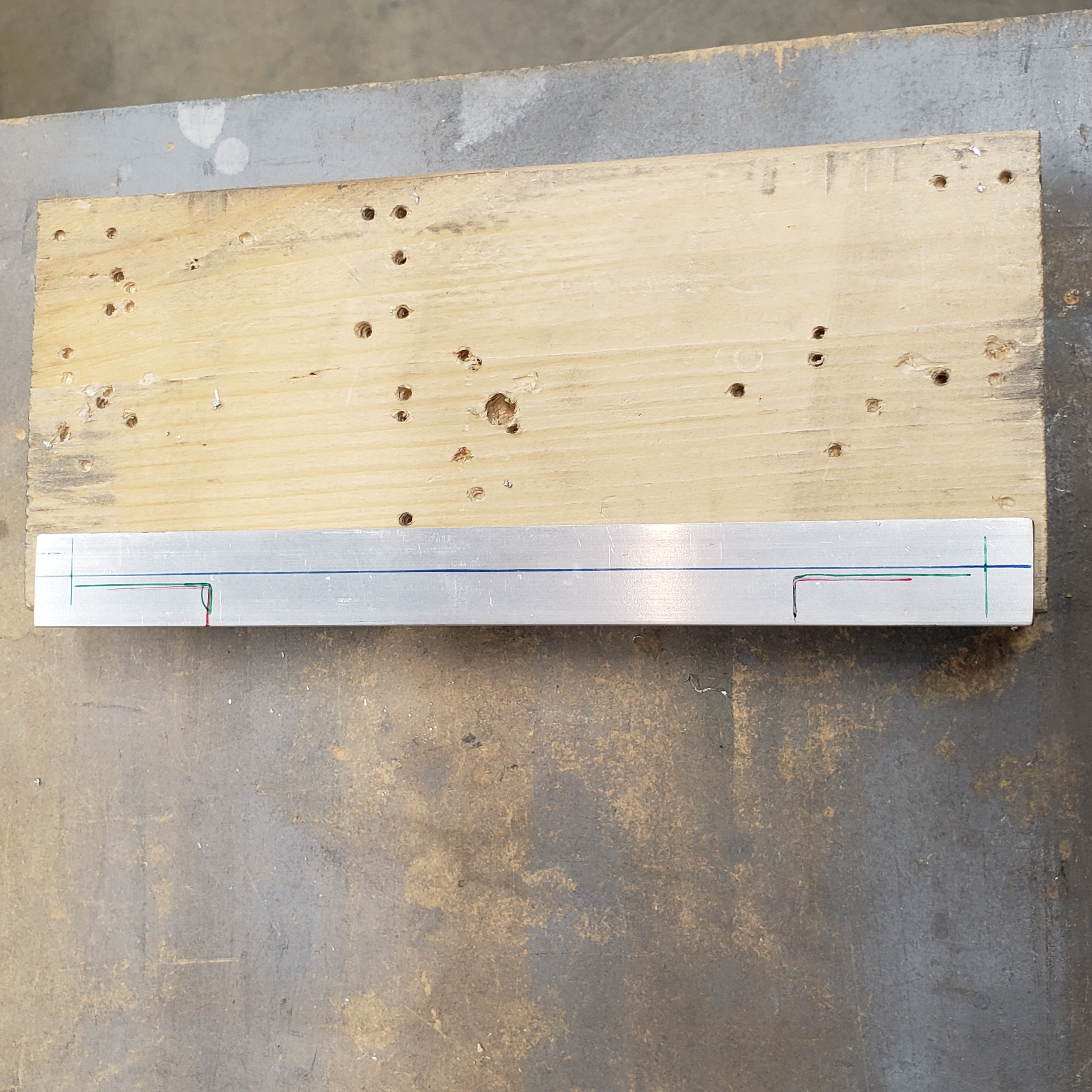
On the backside of the angle, I marked the edge distance and a centerline down the flange that is clamped against the spar. Now with the angle clamped to the spar, I align it by looking through the bolt hole on the opposite side. Here is a view from the aft side of the spar where you can see how the centerline is aligned with the center of the hole and I have the hole center punched. To center punch the hole I used a transfer punch. Now I’m ready to back-drill the hole and match it to the existing bolt hole in the spar.
The key here is to not make the hole in the spar any larger. This is critical. So with a good centerpunched hole to start, work your way up the drill sizes slowly. As you get to being just undersized to the bolt hole, then slowly use a reamer to get the perfect dimension to the bolt hole.
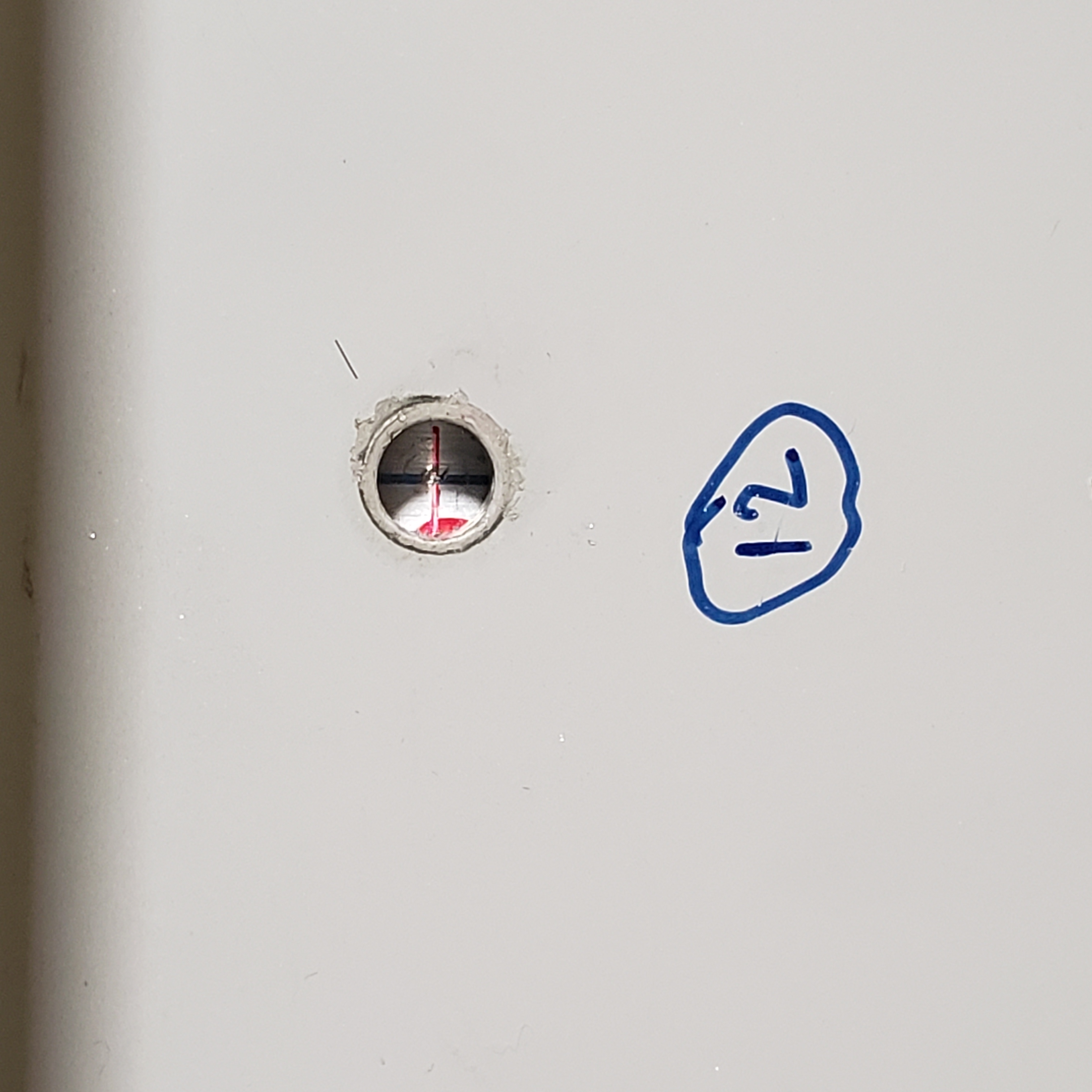
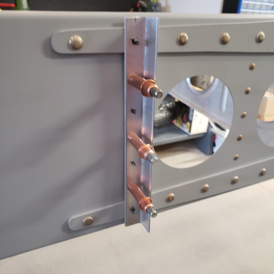
Here the rib is drilled for the bolt holes and clecoed in place.
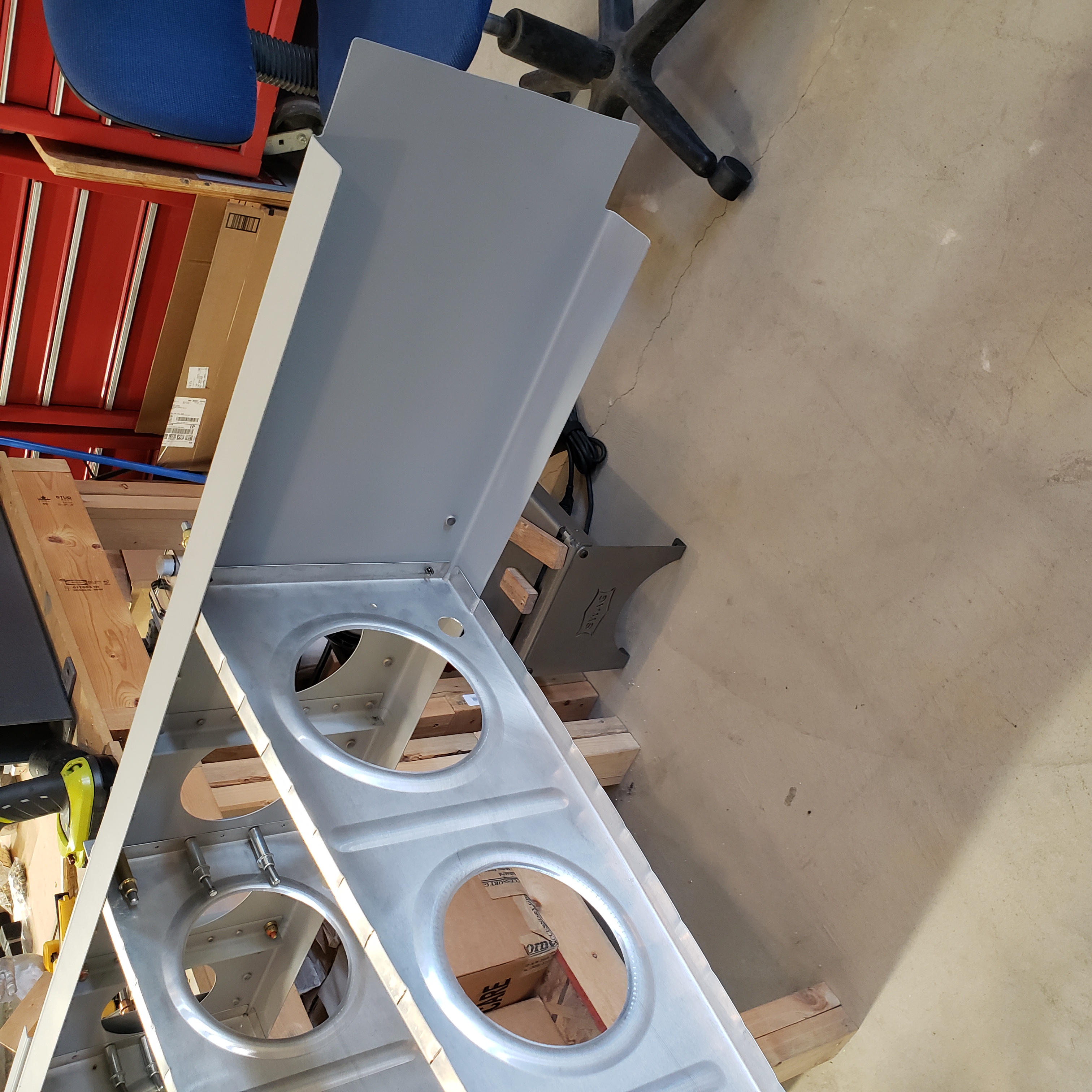
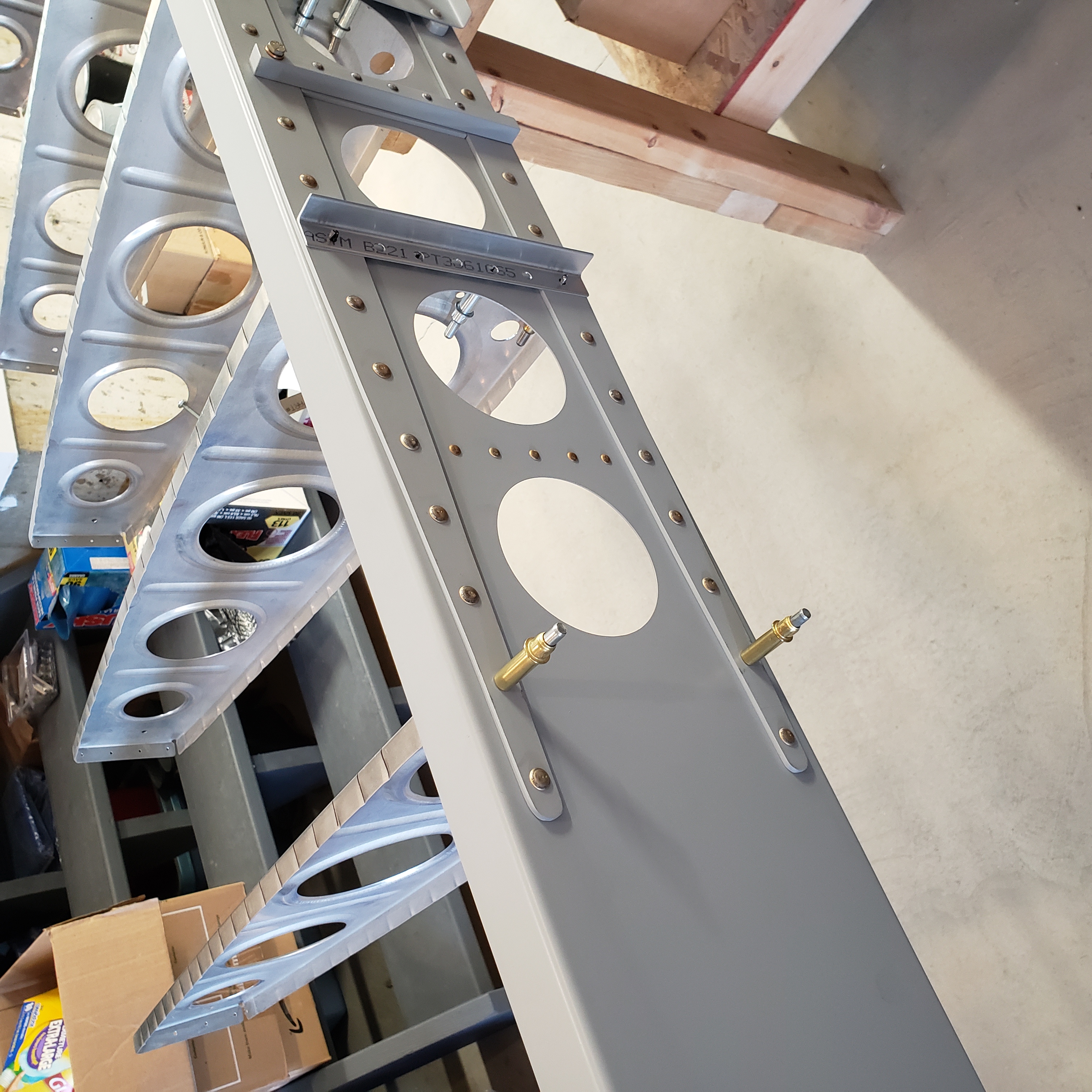
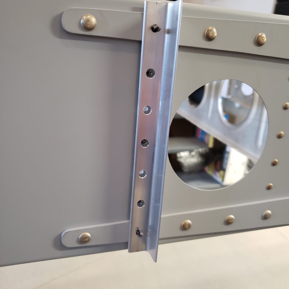
As shown previously, this rib is then drilled along the forward flange for 5 blind rivets. When drilling these, you then need to match drill the angle on the forward side as well. I drilled the rib to the spar first then removed the rib, clecoed the rib and flange together, then match drilled the assembly together on the bench.
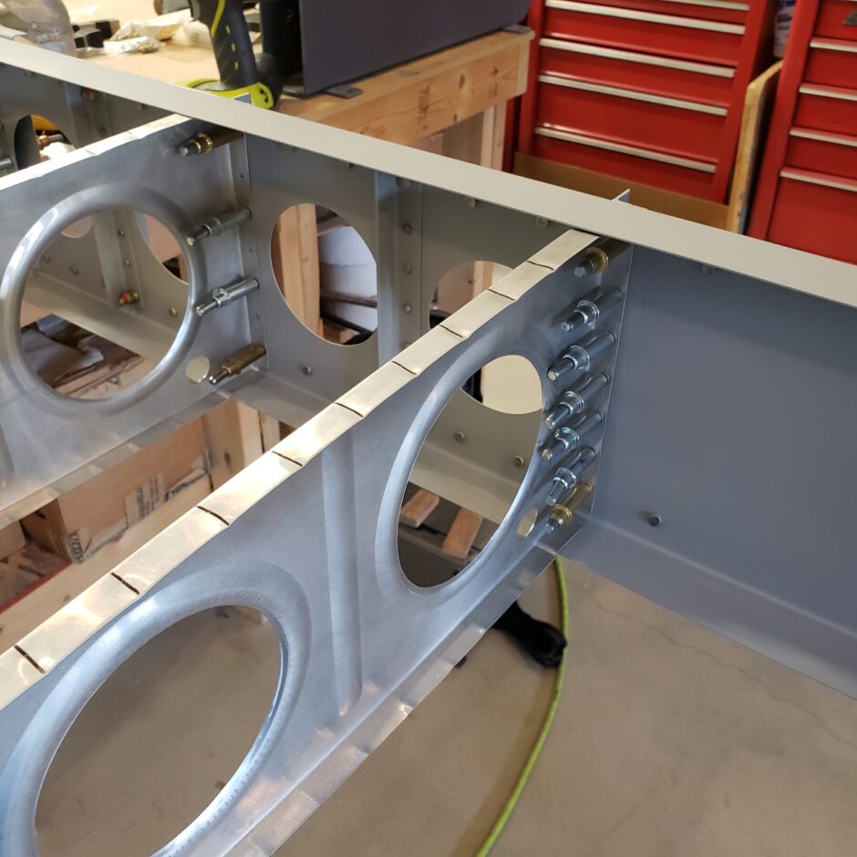
As you can see in this picture, the angle get drilled with a larger holes which will allow the shop heads on the blind rivets to clear the angle.
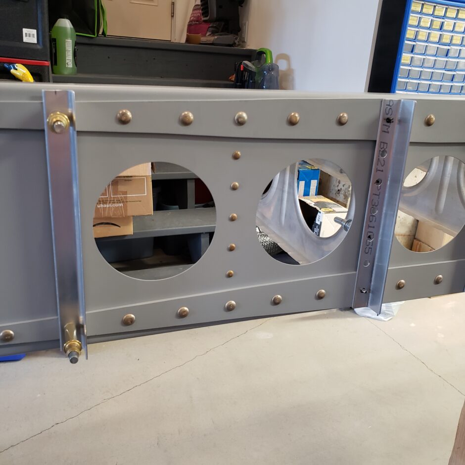
With the 12th rib done, now we do the same on the 13th rib.
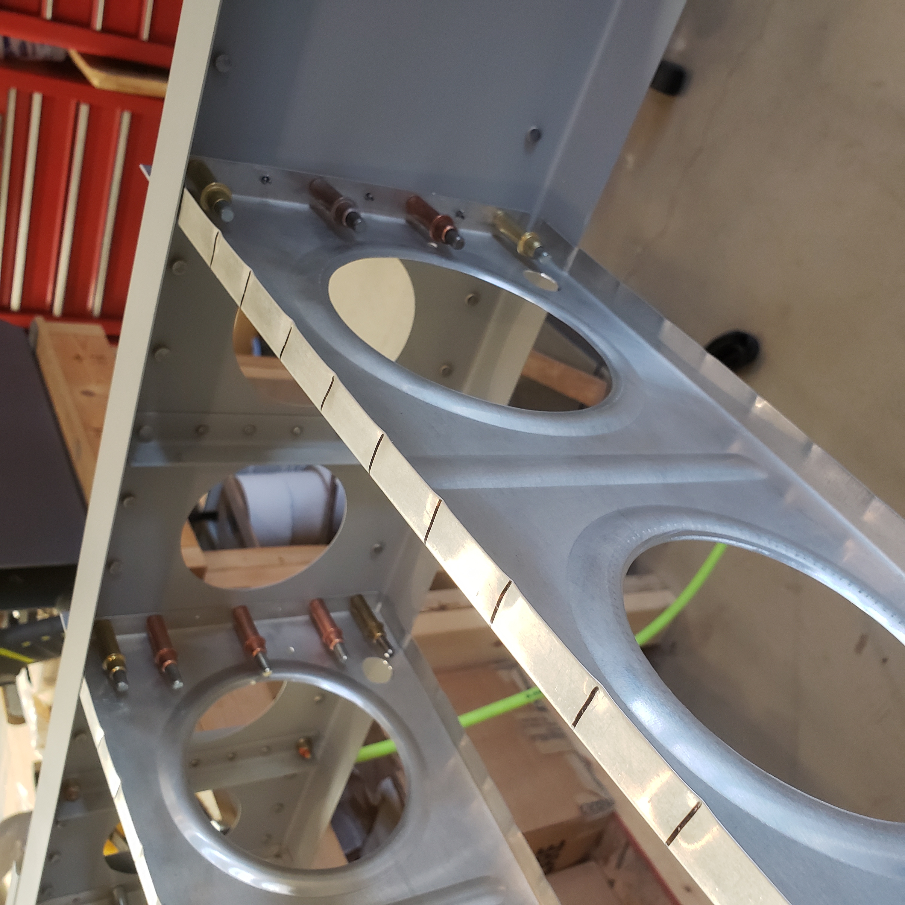
Now that the 12 and 13 ribs are done, I can move onto the end rib. I started by marking the edge distance for the outer rivets, then used the rivet spacing fan to spar out the rest of the row for 8 rivets in total.
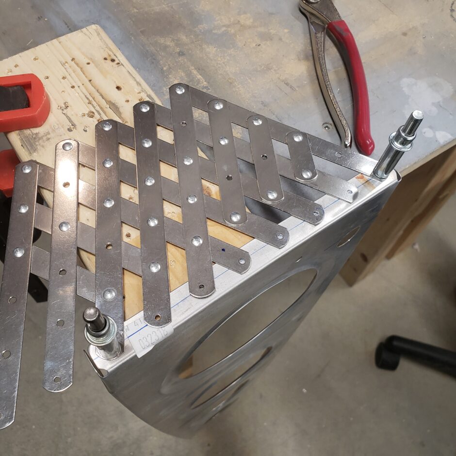
With the end rib drilled, I then clamped it to the spar. Again, like I usually do, I used some scrap metal strips to use as a false skin to help me hold it in place, and in alignment with the upper and lower spar flanges.
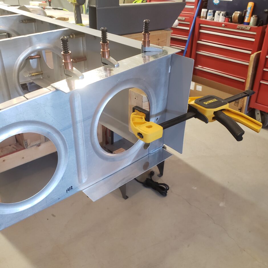
With the rib clamped in place I was then was able to match drill the rib to the spar from the aft side. I did that with a long 12 inch drill bit.
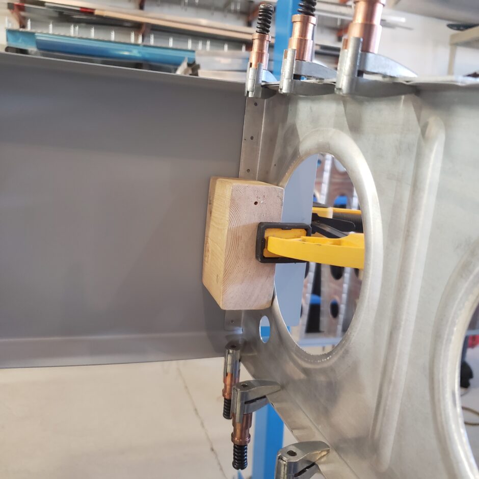
Here’s a shot from the front side of the spar with the end rib pilot drilled to #40.
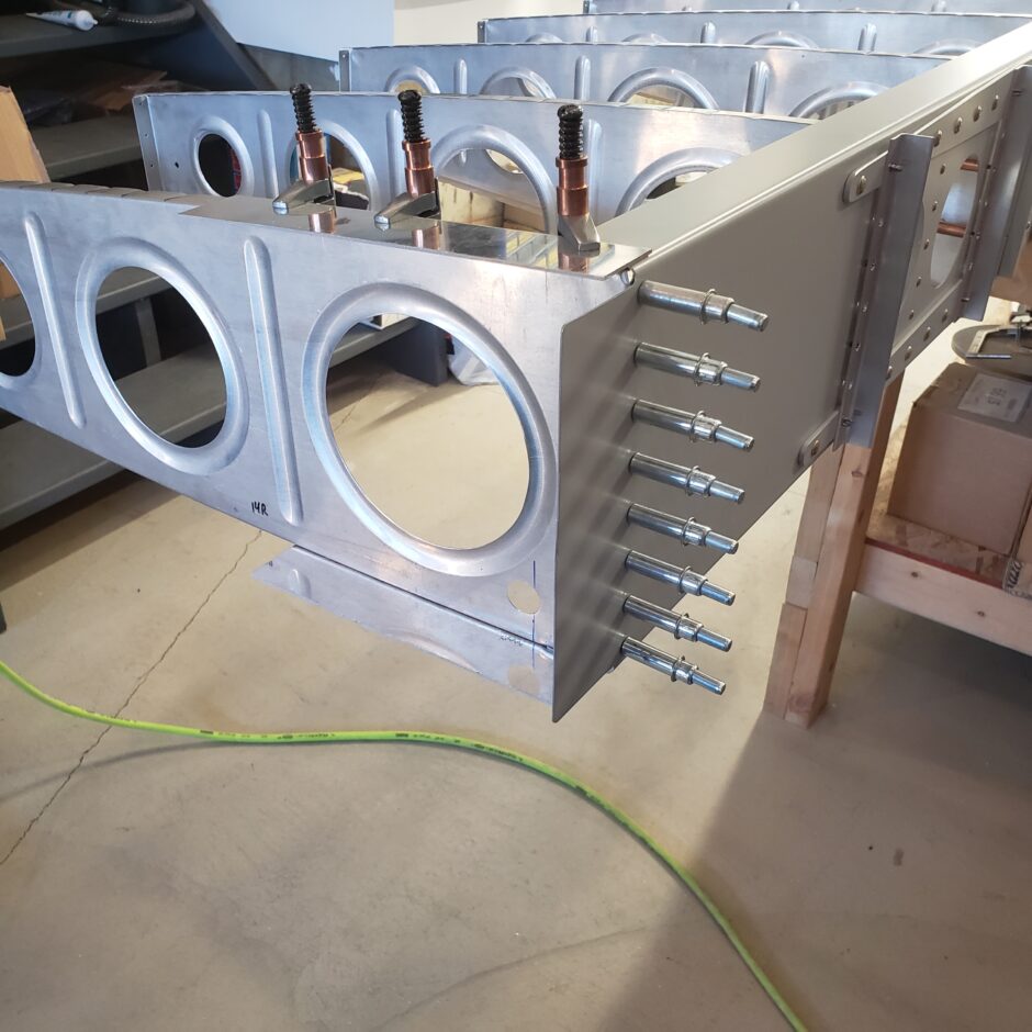
The next step was then to match drill the main end rib to the mating nose rib. I found the easiest way to do this was by working on the flat surface of the work bench. I could clamp the two pieces together and use the scrap strips as a false skin to keep them aligned.
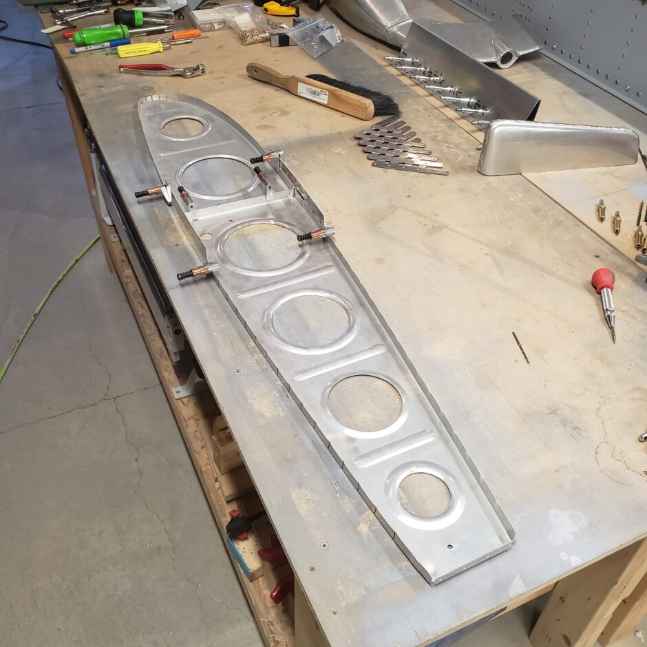
Here a close up of how I clamped the parts together.
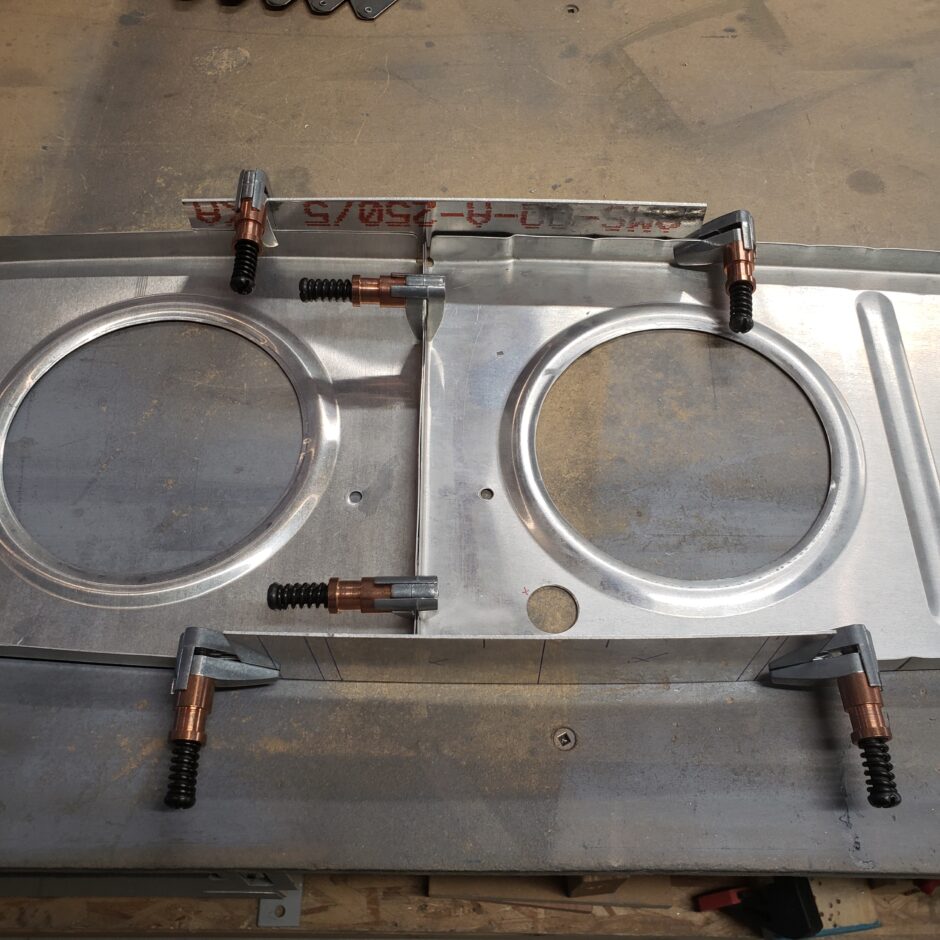
With the ribs clamped, I then had easy access to the spar flange to match drill the main rib to the nose rib.
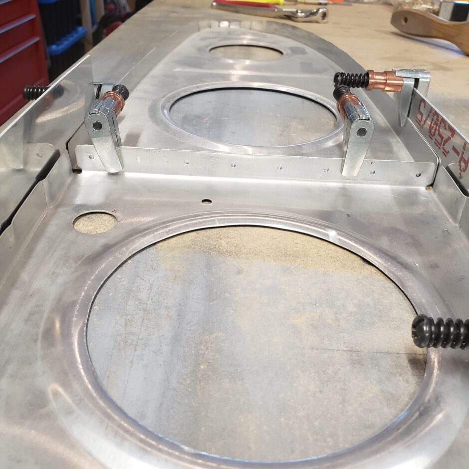
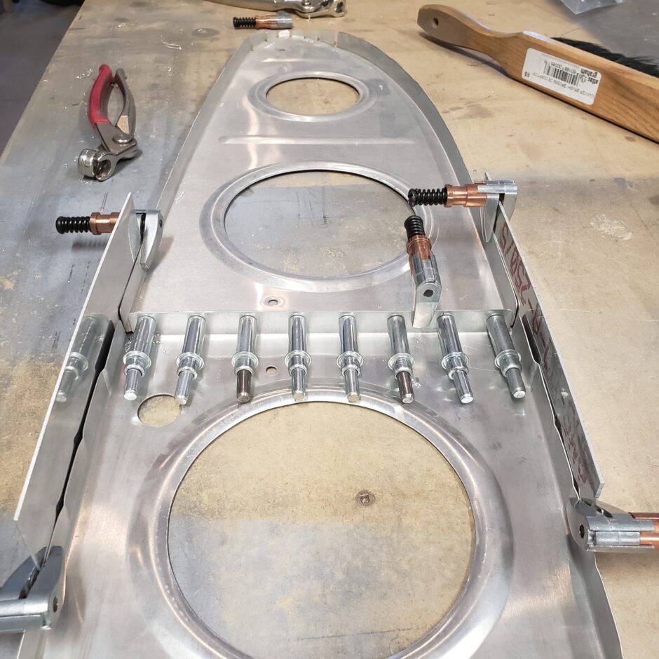
Once the end ribs were match drilled they went back on the spar.
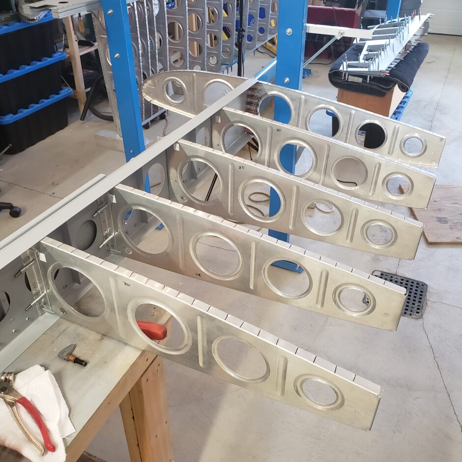
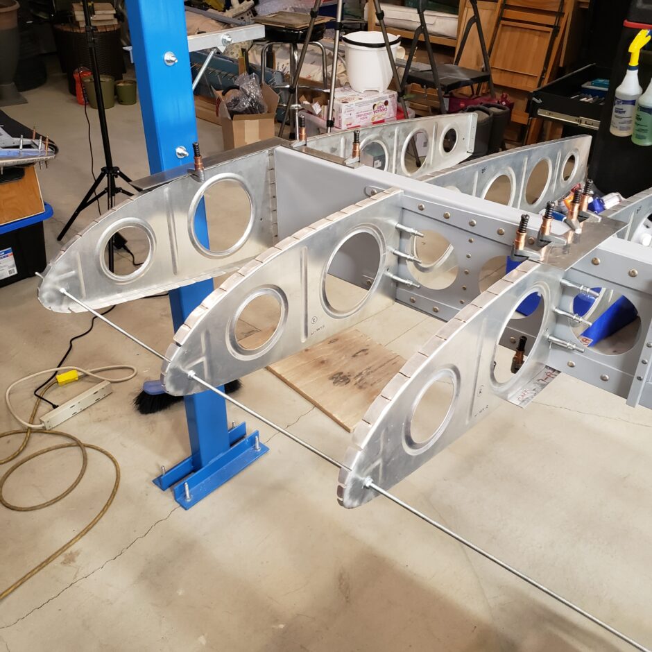
With the nose ribs for the tip and the # 12 and 13 ribs all located, the only remaining rib was the inboard end rib of the fixed leading edge (or what I call the 11.5 rib). This is the rib immediately outboard of the fuel tank outboard rib. This is installed very similarly to the 12 and 13 ribs.
In the picture below, you can see that I have an additional strip of aluminum clamped to the rib. This is the screw flange that will eventually join the fixed leading edge skin with that of the outboard fuel tank. I needed to add this strip in place as the 11.5 nose rib is slightly smaller in dimension than the other nose ribs because of this screw strip.
With that screw strip in place, I then also added the standard “false skin” strips to help me hold the rib in alignment with the upper and lower spar flanges.
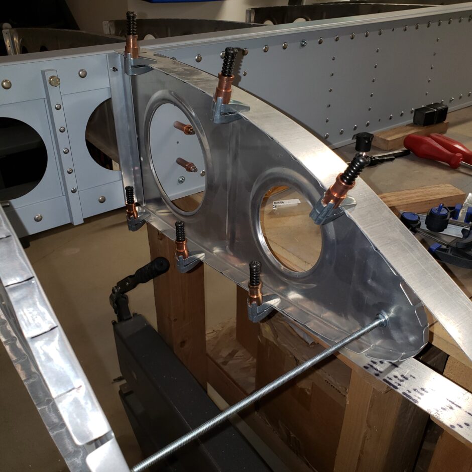
The next dimension to get set is the positioning of the 11.5 nose rib fore and aft, so that the leading edge of this rib (with the screw strip) is flush or even with the tips of the other nose ribs. Remember, the leading edge skin has to sit evenly against the tips of all these nose ribs.
The way I set this dimension, was by measuring the distance from the spar to a tooling hole (which I used to hold the threaded rod, which helps me set these ribs close to 90 degrees perpendicular to the spar.
As you can see in the next few pictures, this dimension is working out to 16-inches for me.
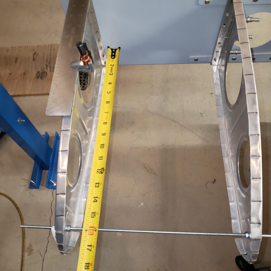
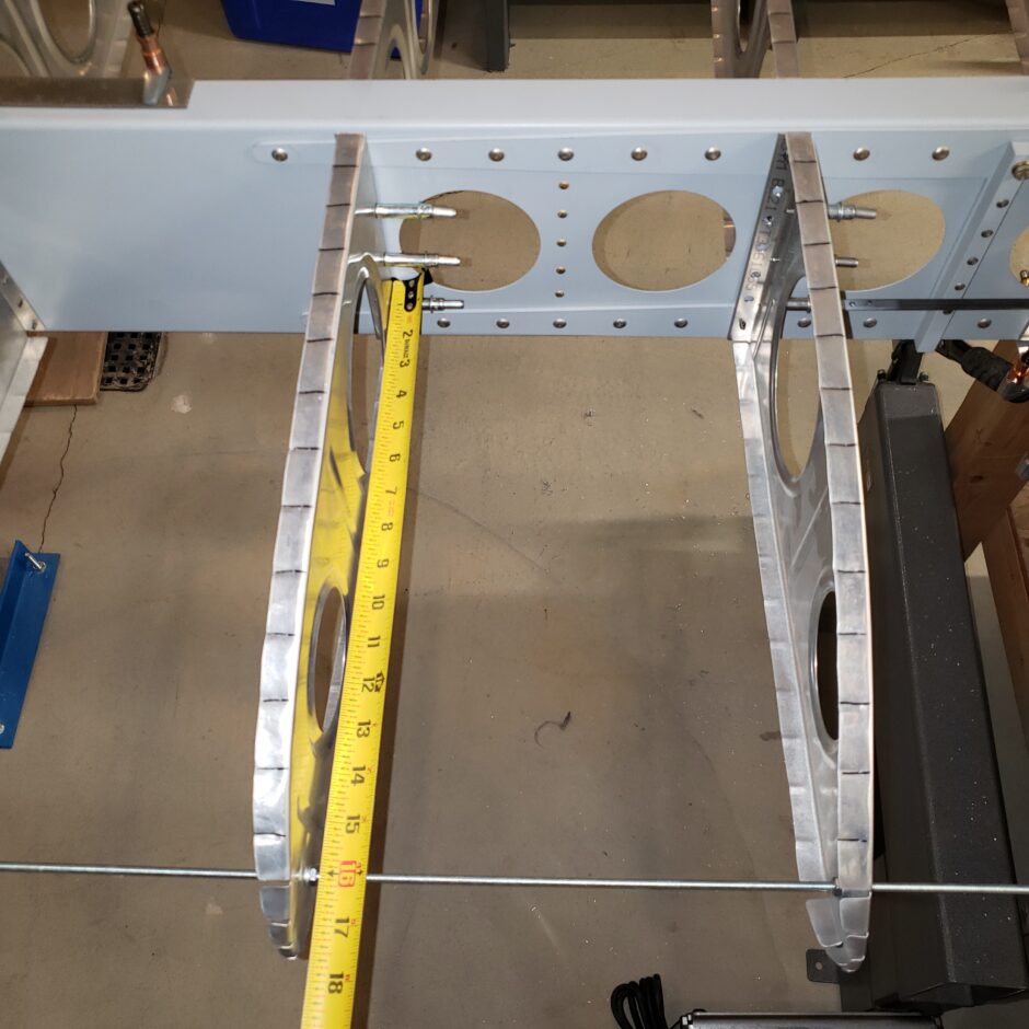
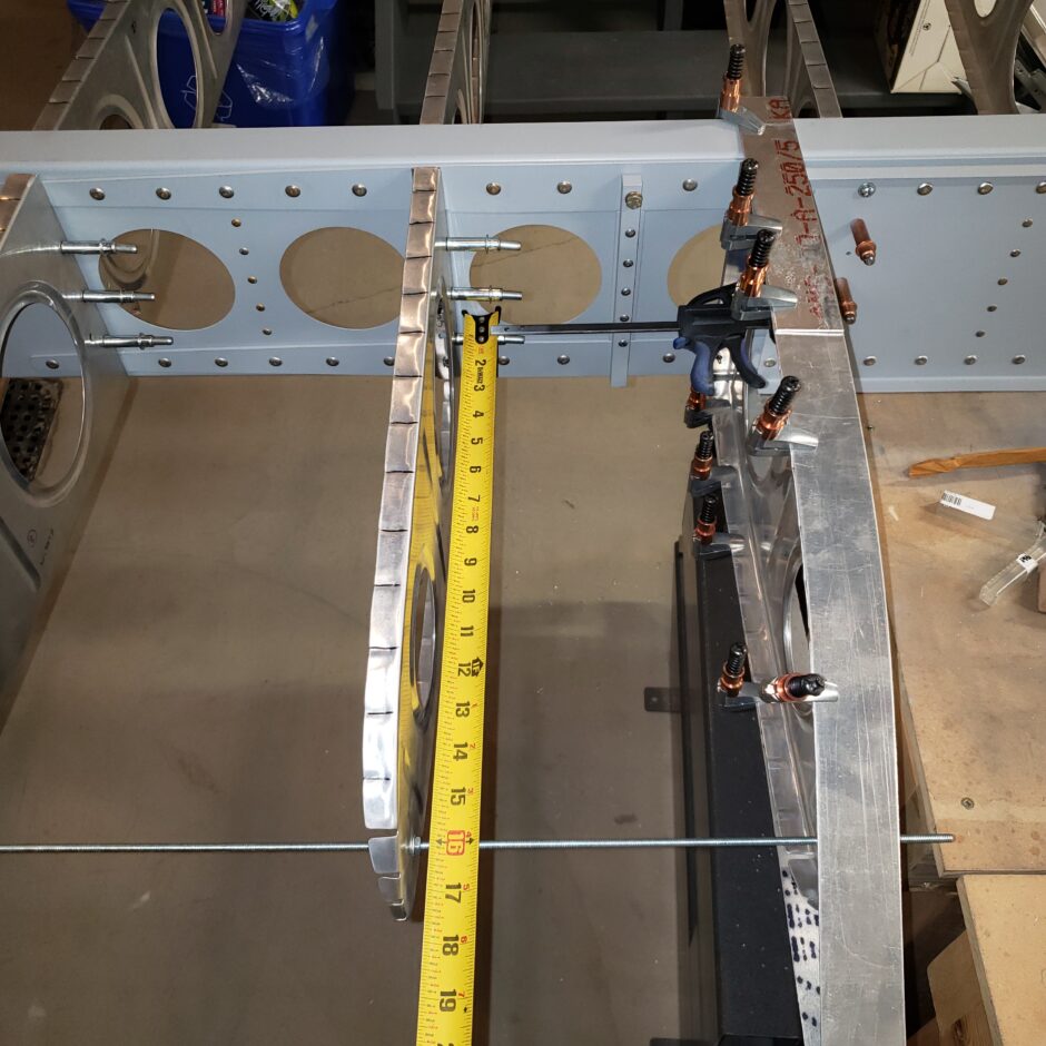
Once all those dimensions were checked with the other ribs, I clamped the 11.5 nose rib securely against the attach angle and then traced it’s location on to the attach angle. As you can see, this rib has some additional cut outs as it normally sits much further inboard, and needs to straddle the spar beams. So you want to make sure you have good edge distance from all these areas, and then you can evenly place the 5 rivets between.
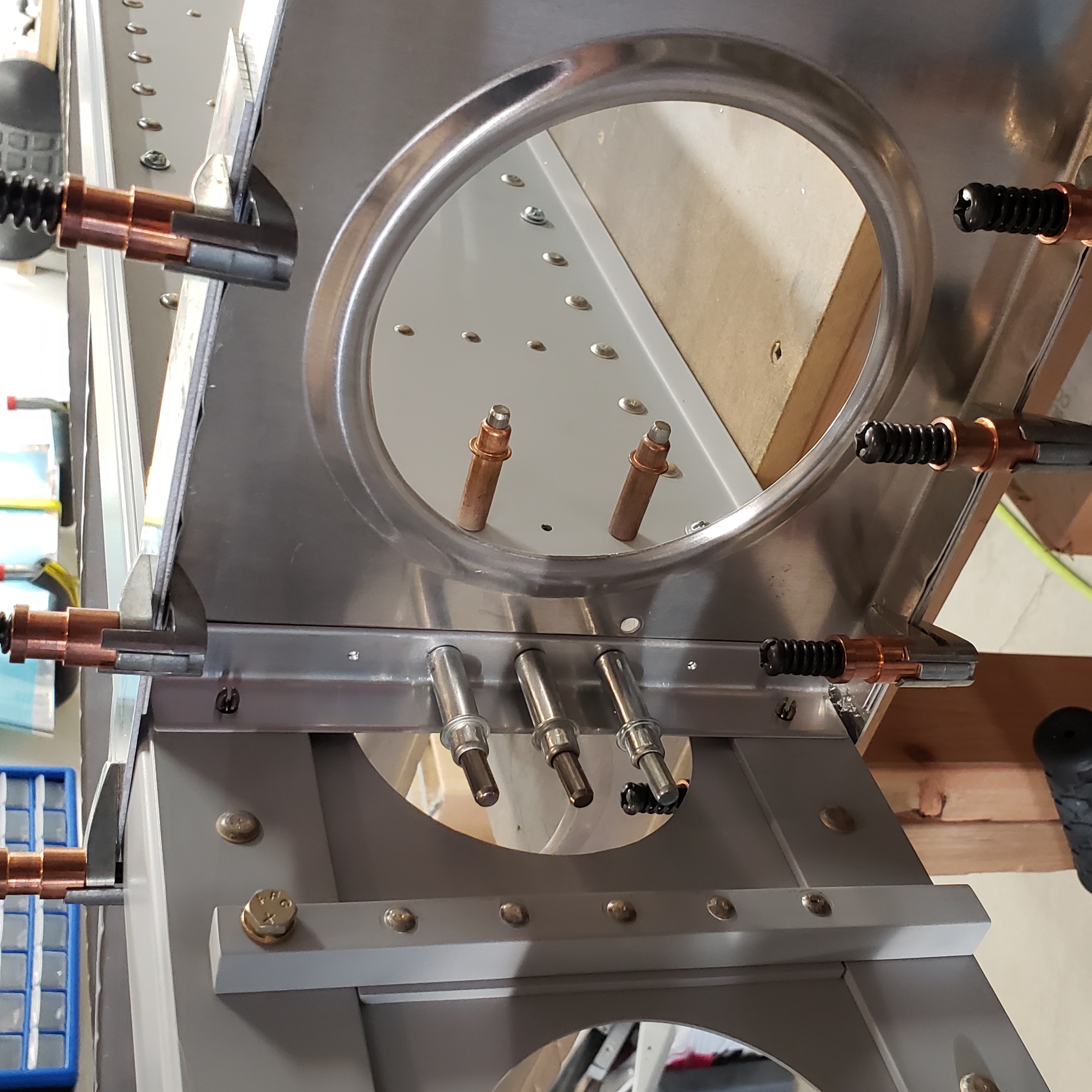
This picture below is a good shot of how the rib is cut out for the spar beams. This is why its important to mark all these parts correctly before you start to do any drilling.

Here’s the other side of the 11.5 rib drilled to the attach angle. Again, here you can also see the false skins I’m using to help me with the alignment of the rib to the spar flange.
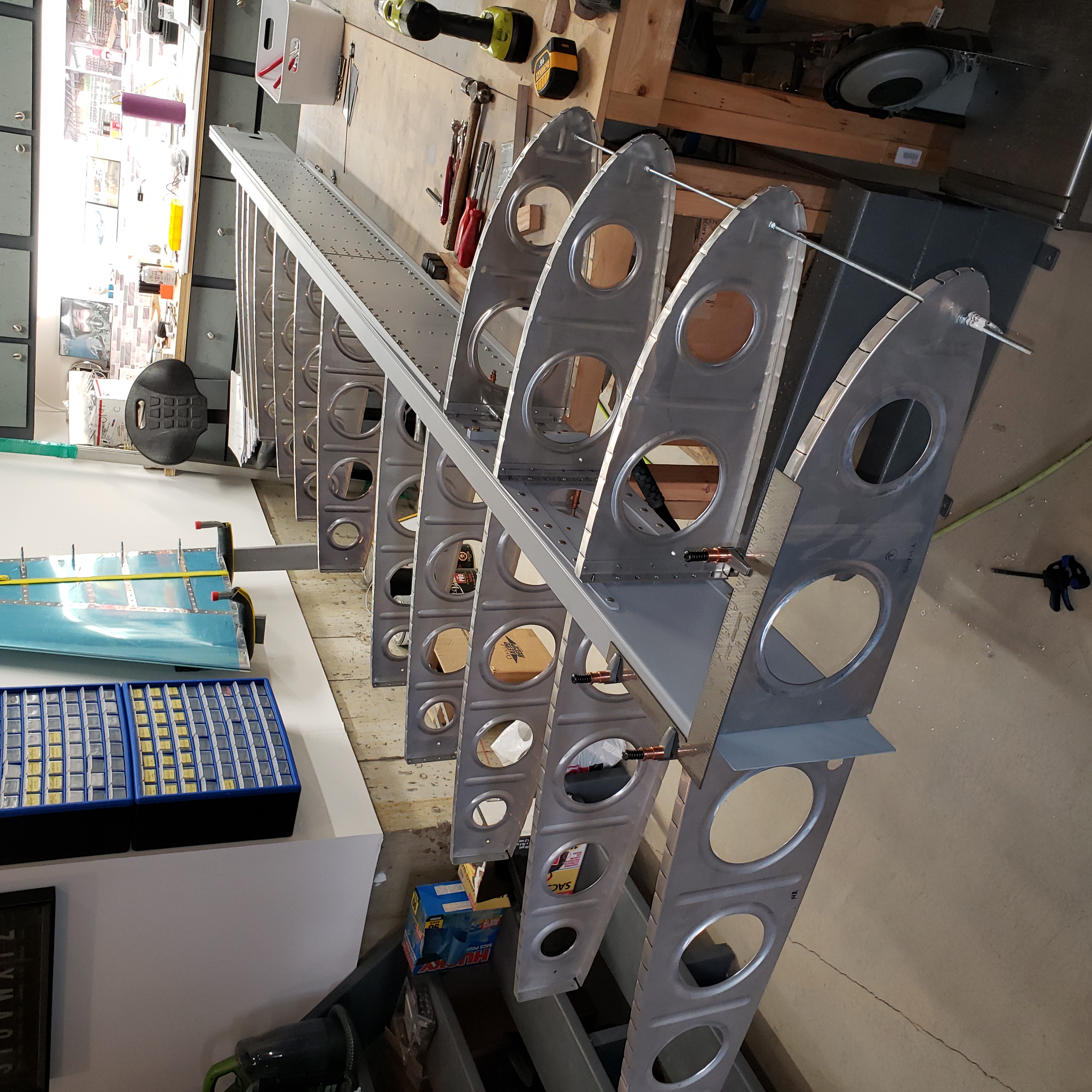
And just like that, the leading edge ribs are all located. The only thing left to do now is to install the aileron bellcrank rib.
That’s all for today folks! Please comment. I love to hear from my readers. Thanks again for coming along for this ride, you make my work worthwhile.
Good day!
Leave a Reply