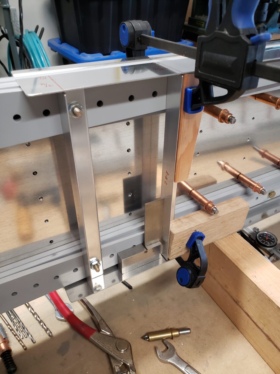
Today I’m working on locating the attach angles for the wing ribs. This isn’t too difficult, however you need to make sure that you keep the perpendicular to the spar. A machinist angle works well here.
I start by marking the centerline on the angle, then aligning it on the spar so that you can see the line centered in the appropriate spar bolt hole. Then clamp it in place and drill. I also used a transfer punch to confirm that I had the center of the bolt hole properly located on the angle center line.
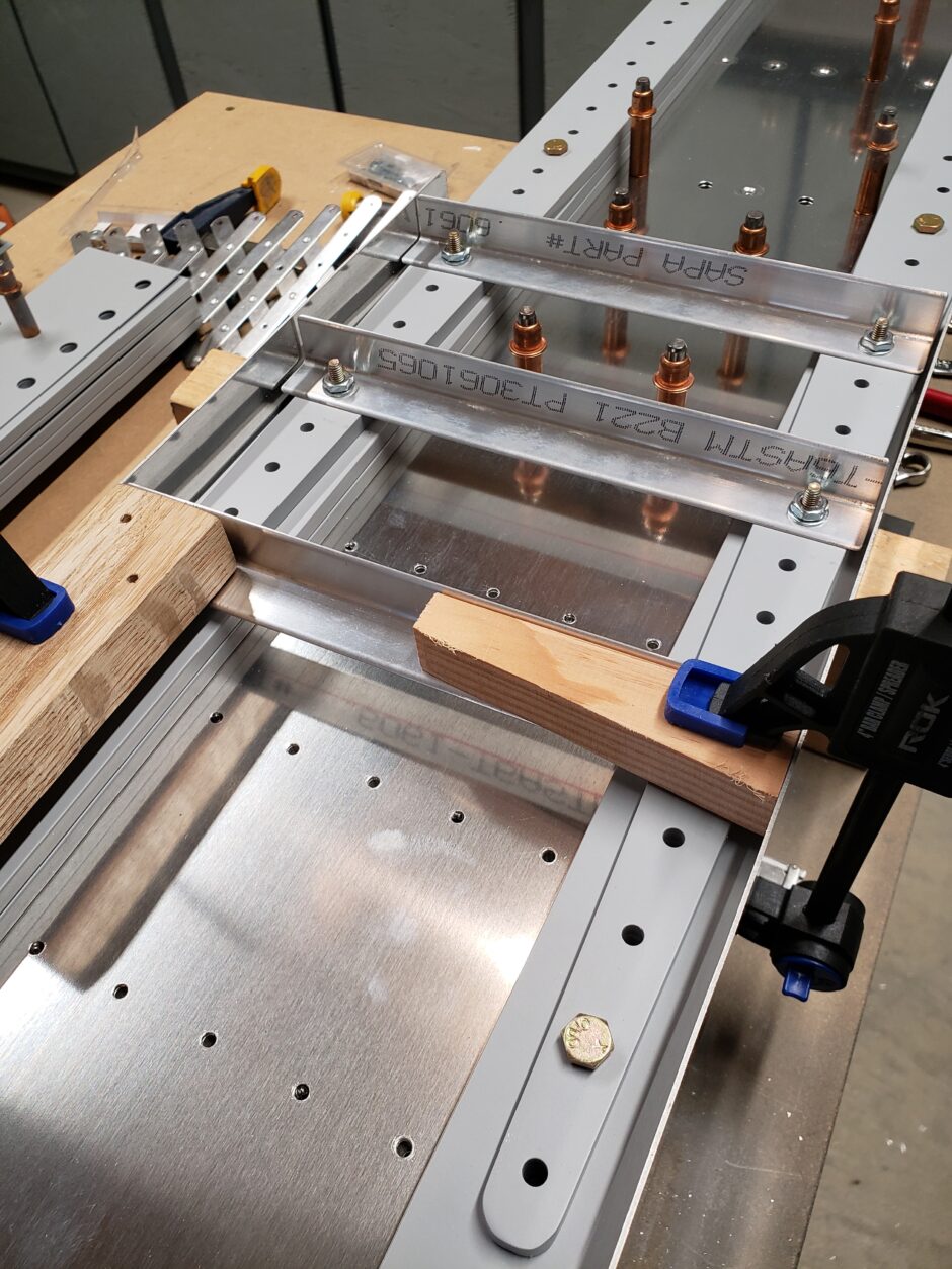
The rib angle spacing was pretty straight forward until I got to the number 9 rib. As shown in the picture below, I was doing a lot of head scratching and comparing dimensions between the HRII and F1 drawings. Both of these have the number 9 rib location close, but not really lined up with the pre-drilled spar bolt holes.
To complicate things further, I’m heeding the advice provided by Mark Fredrick though build comments on Vince’s Rocket website, which talk about reversing the aileron bellcrank rib, W-11L, so the flanges point inboard. This potentially eases the installation of the aileron bellcrank support angles.
In the photo below, you can see the number 9 rib angle is backward (flange inward) to accommodate this suggestion.
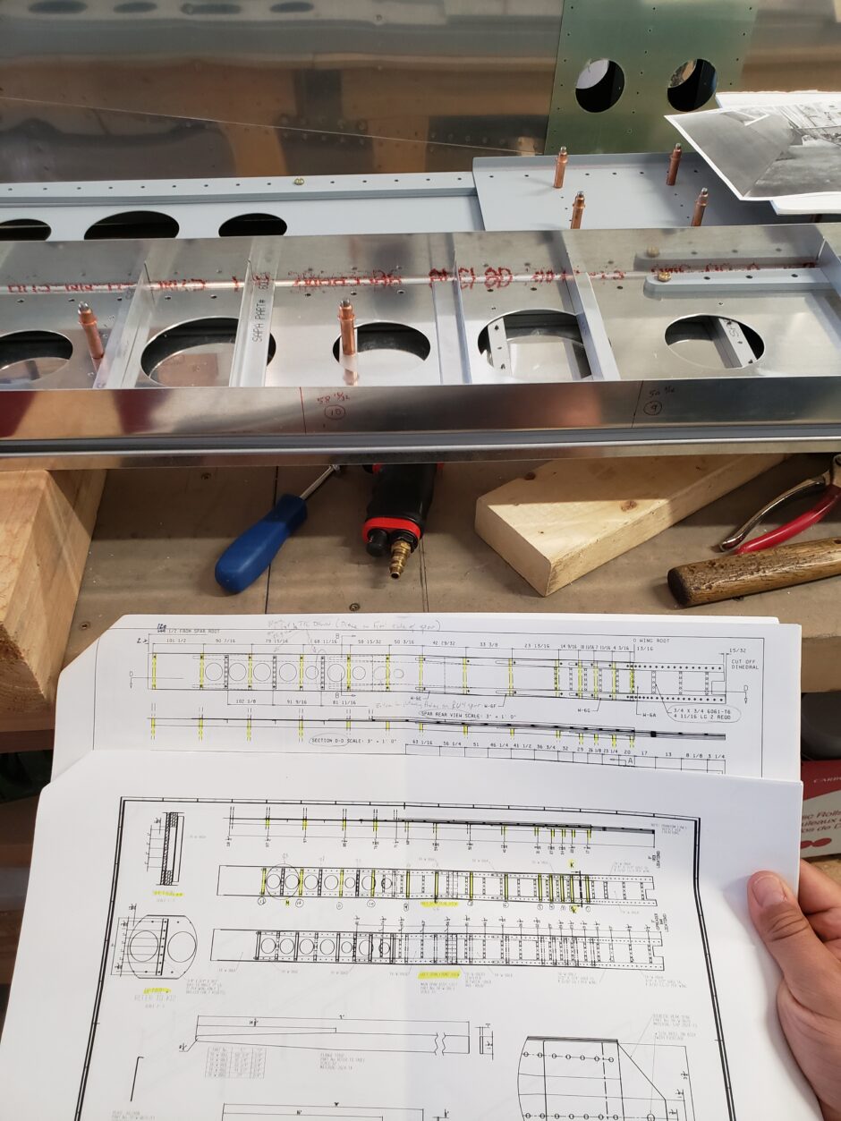
Getting back to how the rib locations don’t really line up with the pre-drilled spar holes, what you need to do is just pick the hole that is closest to that particular rib location and scootch the rib angle over a bit to line up. Don’t worry about being exactly to the plans measurements here. I was striving for that and wasted about a week or so of trying to find a good answer (evident in the picture below as I’m comparing the plans trying to determine what to do)… Just move the rib over slightly to line up with the closest hole.
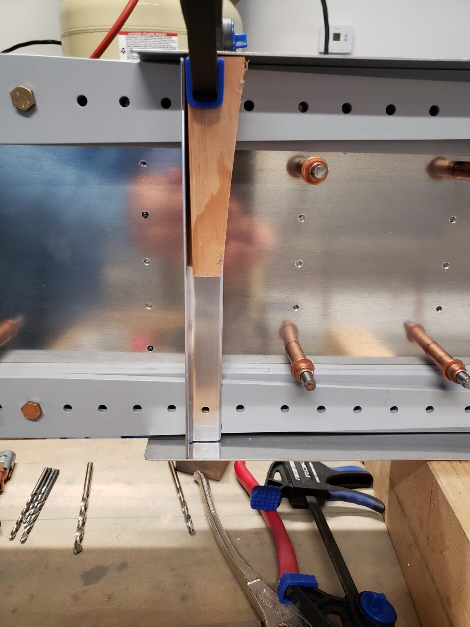
Below you can see one of the holes completed as I back drilled.
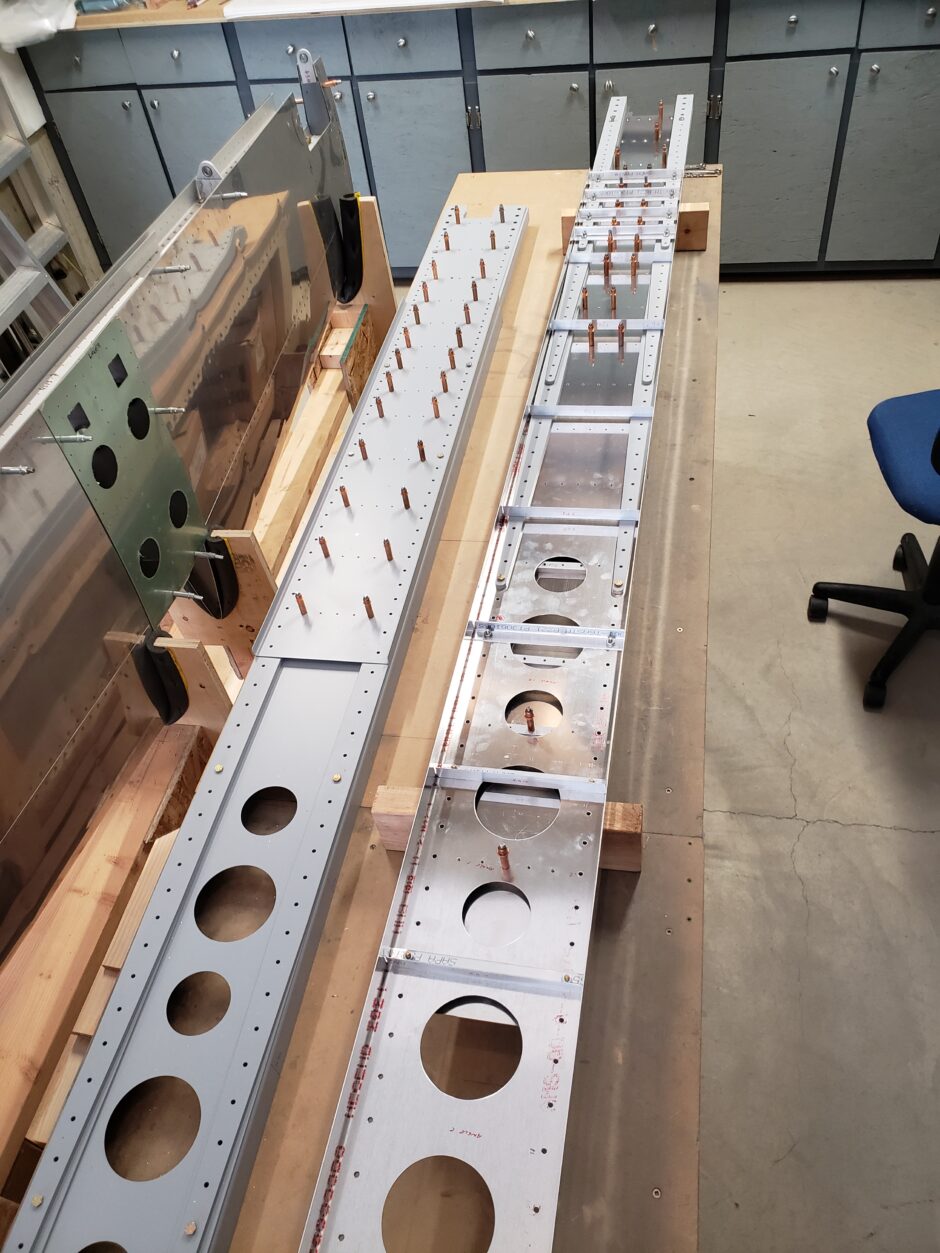
Below is a good overall view of the spar with the rib angles located. Lots of repetitive work here.
Spar Stiffener Angles
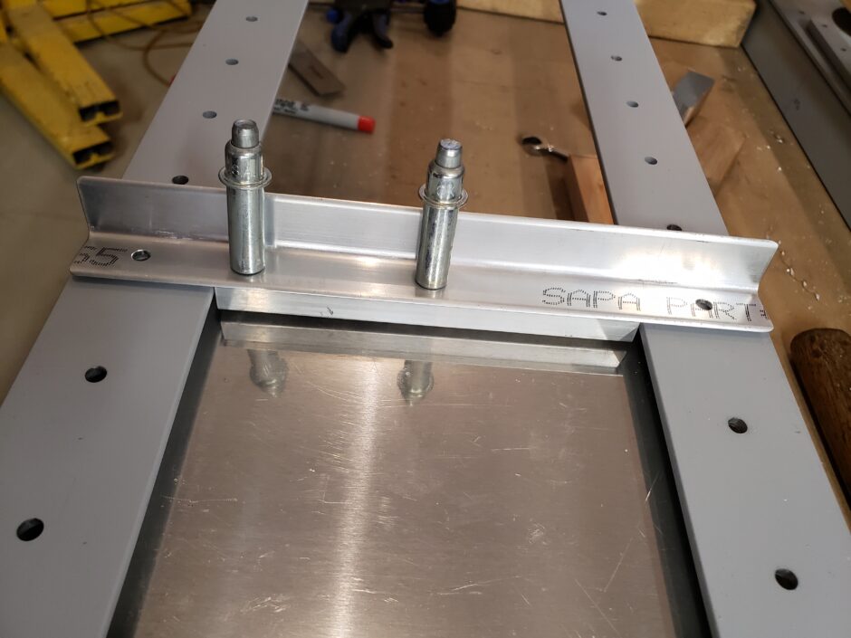
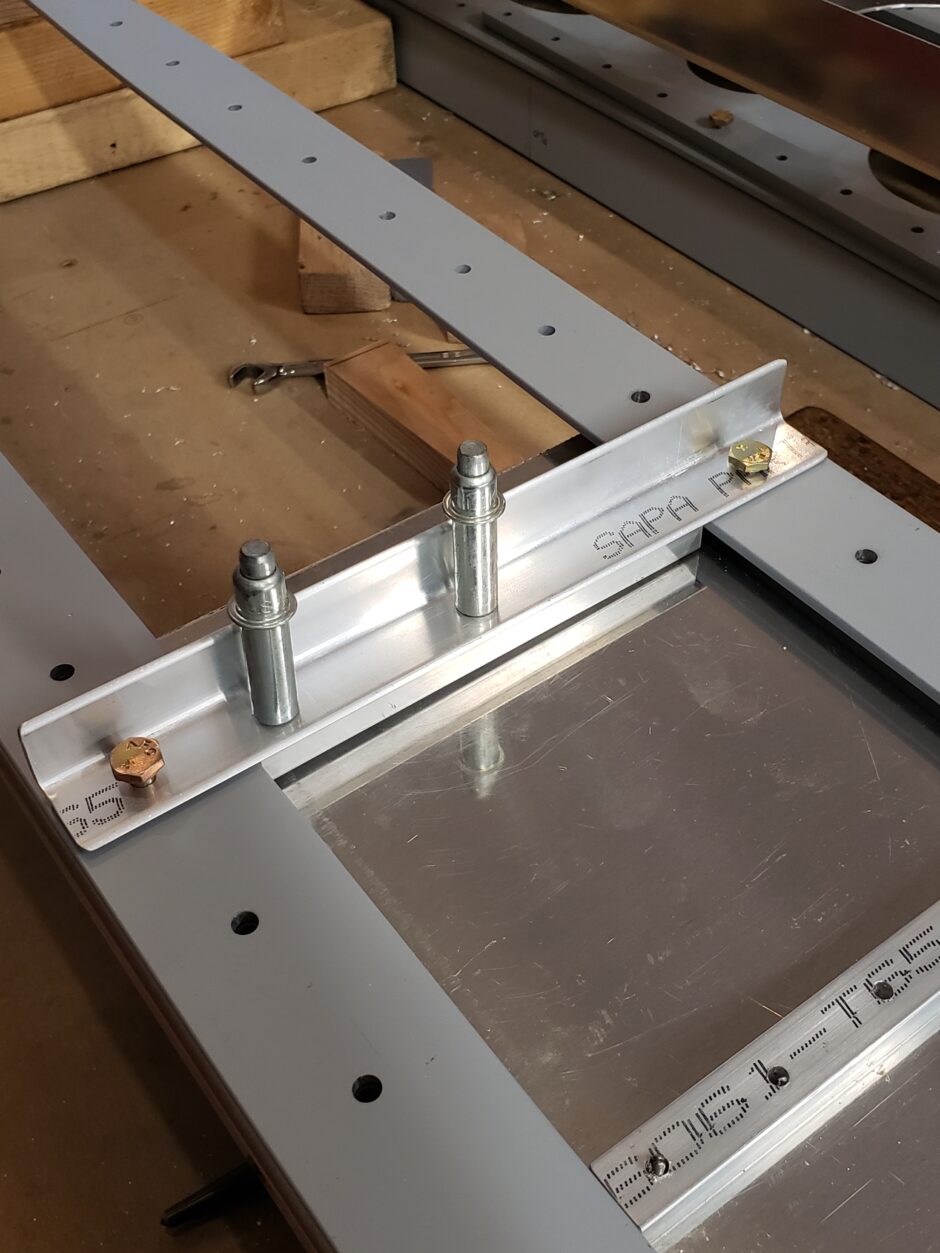
At the outboard end of the spar, there are 3 spar stiffener angles that need to be added between some of the lightening holes. As these angles are a bit shorter than the rib attach angles, you need to pay attention to getting them centered.
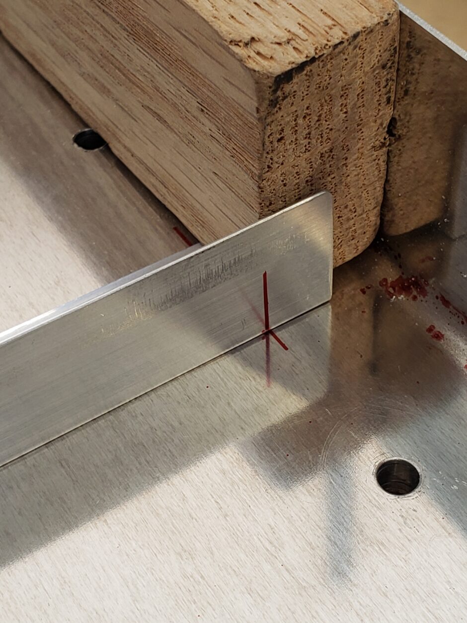
I started by marking both the edge distance for the bolt holes on either end of the angle. I also marked spanwise across the center of the bolt hole so that when I have the angle over top of the holes, I can see how close my angle measurements are to that of the actual pre-drilled holes.
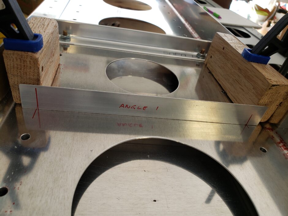
Below is a closer view of the alignment marks. Some were pretty close, and others I just split the difference to get both holes centered (or balanced) on the angles.
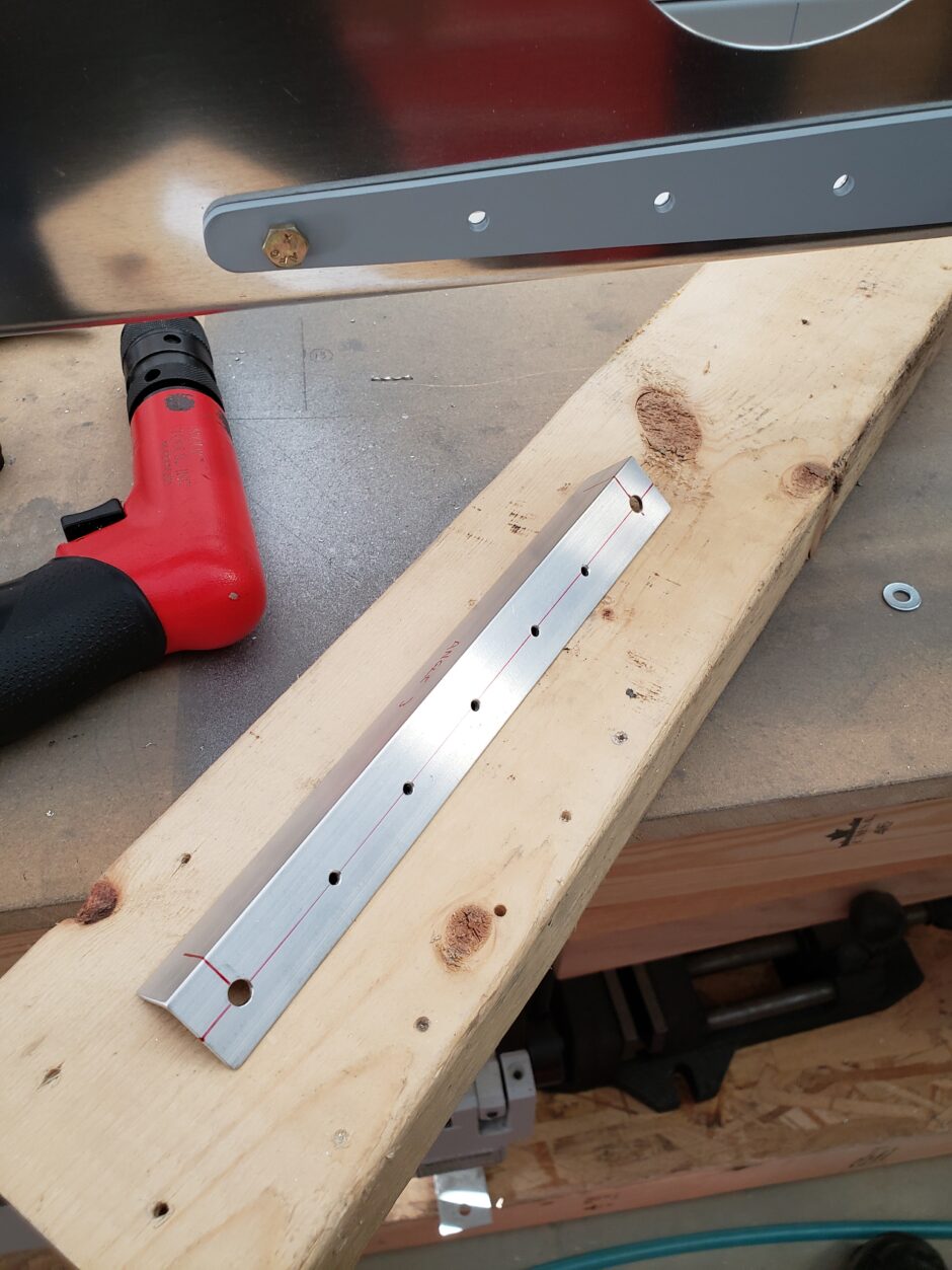
Once I had the bolt holes drilled I laid out the center rivet line.
Once the rivet pilot holes were drilled in the angle, I fastened the angle to the spar and back-drilled the pilot holes.
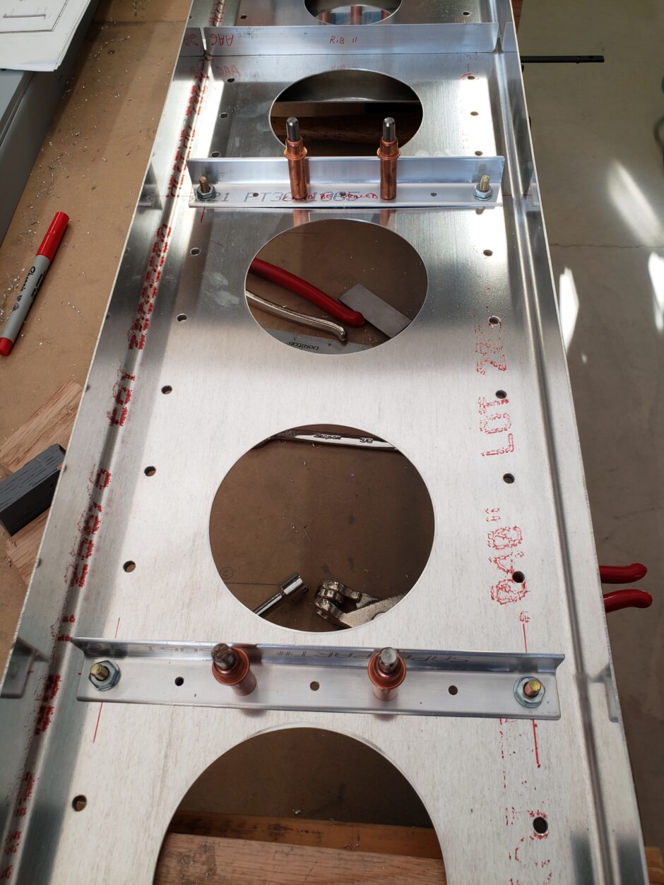
One of these angles also spans the same location of one of the additional spar web spacer blocks added for the forward spar web doubler extension. The angle was back-drilled to match the pilot holes of the spacer block.
Wing Spar Rib Spacing Dimensions
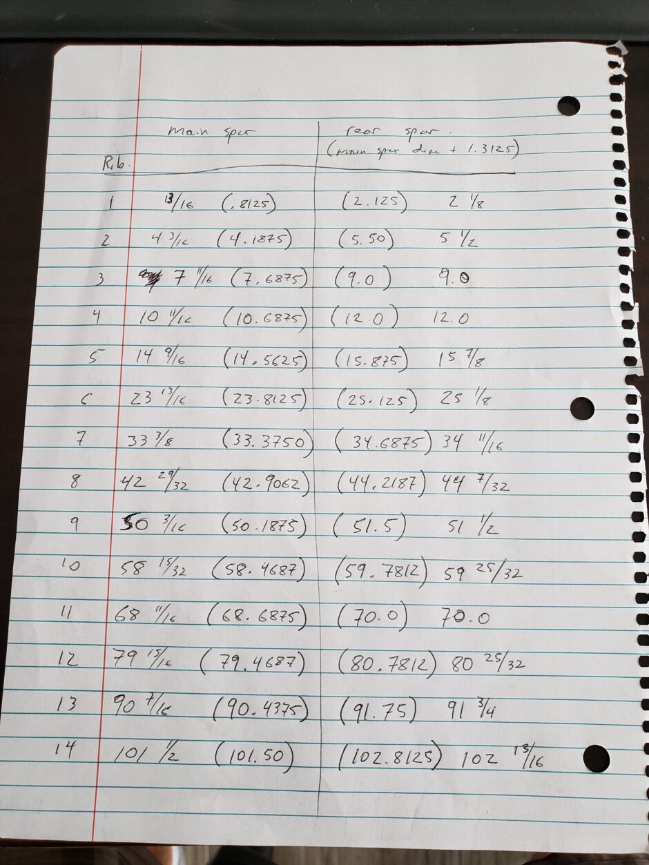
Well, now that you’ve read all the way to the end of this post, here is my value added page of notes with all the rib spacing dimensions that I used, for both the main spar and rear spar. As mentioned previously, for the ease of my understanding, I identified each rib by a number 1 through 14 (inboard to outboard) rather than always referring to the dimensions.
I hope this will save you future builders a whole bunch of time!
Please comment. I love to hear from my readers. Thanks again for coming along for this ride, you make my work worthwhile.
Leave a Reply