The work in this post was done during the week of March 01 – 06, 2020. The work was just too scattered to warrant a single post for each hour here and there of building. Interspersed was also quite a bit of time reviewing the plans and other builders websites to figure out how to actually get the trim tab hinge installed.
I found that the Van’s instructions for this area were not very clear, from a step-by-step guide for this critical area. The instructions state in part…”Use the dimensions given in DWG 4 to position and clamp E-721 (trim tab hinge) to the top flange of E-607PP (trim tab spar). Mark the inboard edge of E-619PP-1-020 (trim tab skin) and E-607PP on E-721.” Then the instructions go on to say to drill it.
I understood what needed to happen, but I didn’t want to drill anything yet until I knew that I would have the trim tab properly in place and in alignment with: (1) The trailing edge of the elevator, (2) equal gap spacing along the hinge, (3) alignment with the inboard end of the elevator. Which is why I started looking at other build logs to find alternate ways of accomplishment. What I found was quite varied. Some people start at the inboard end, some start at the outboard end and of all the ways, I didn’t come across one who actually showed that they followed the instructions step-by-step.
Trim Tab Control Horns
Before we get too far ahead of ourselves, lets go back to where I started. Don’t forget that it’s been a little over 2 years since I’ve had time to build. So the point that I left off on the trim tab was making new control horns (E-717 and E-718). The control horns supplied with the RV-8 kit are fabricated from 0.032 inch aluminum and for the F1, these needed to be made from 0.040.
To get a template to start with, I hammered the kit supplied control horns flat, then traced them on some 0.040, then began cutting, trimming and filing. Below you can see the progress.

The tough part for this was figuring out where the bend line was. I actually ended up making these parts 2x because they didn’t match up after being bent.
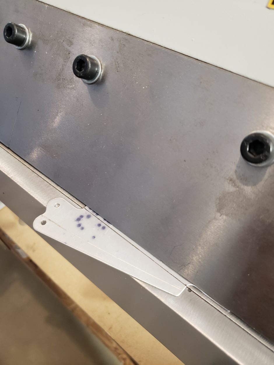
And here are the finished products.

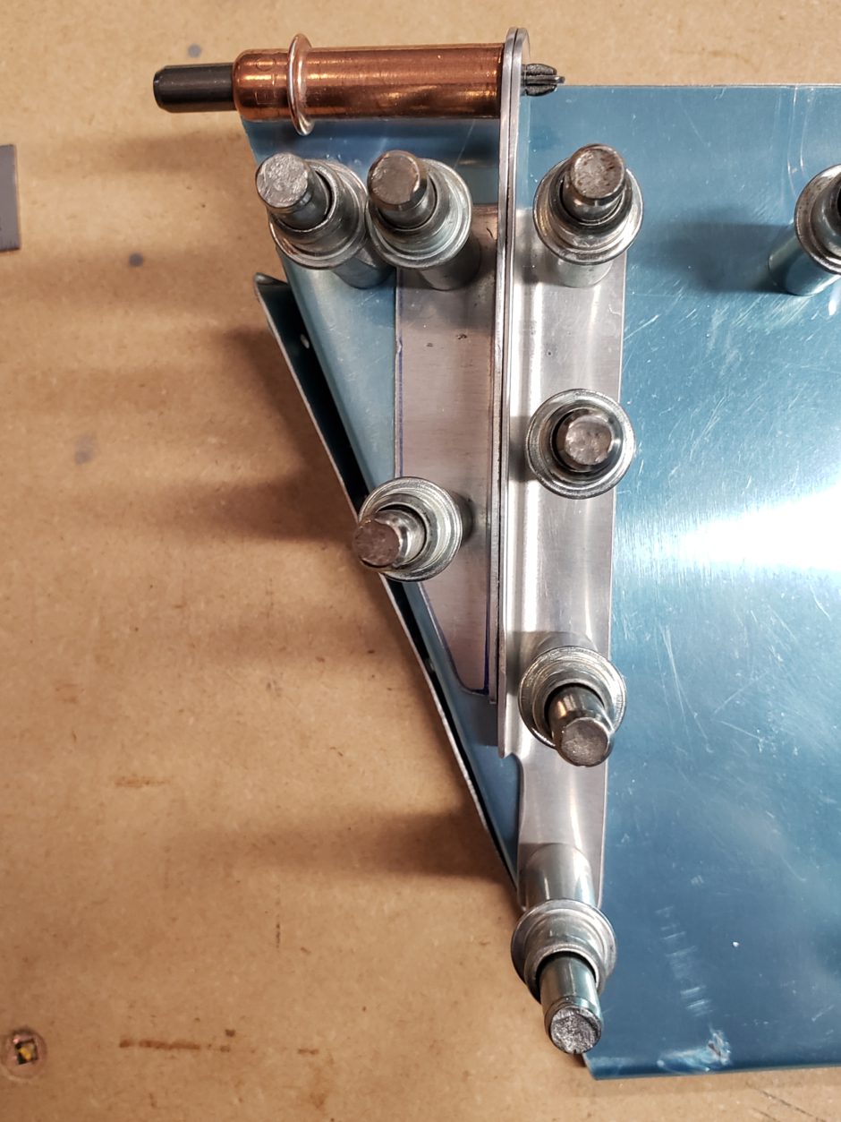
Getting the control horns in place on the trim tab was no big deal. Just line up the predrilled holes, cleco and pilot drill.
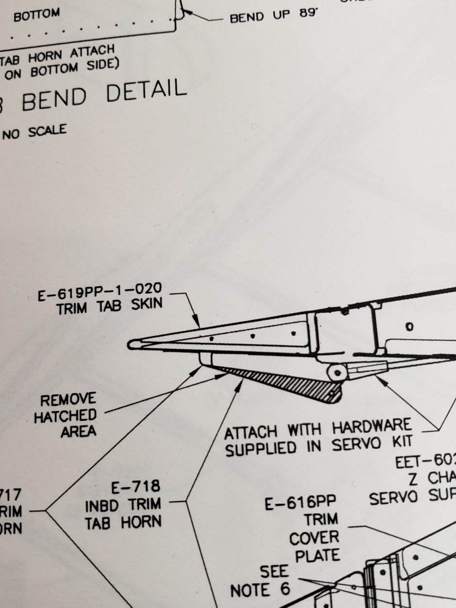
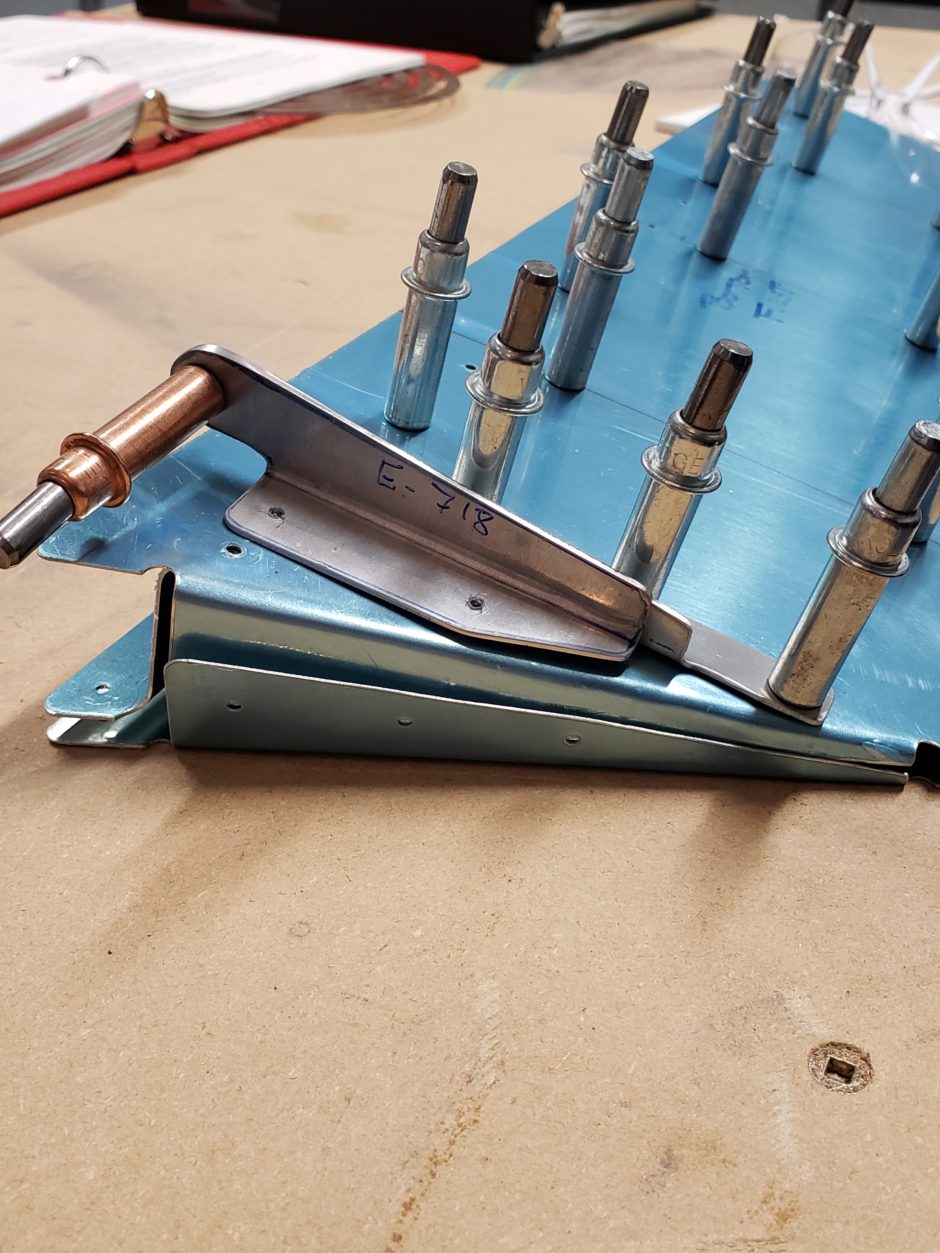
The plans also specify that you need to trim off the unused portion of the control horn. So back to the scotchbrite wheel!
Trim Tab Hinge
As discussed above, this wasn’t as straightforward as the instructions may seem to be. Like everyone else, I blazed my own trail and it all worked out in the end.
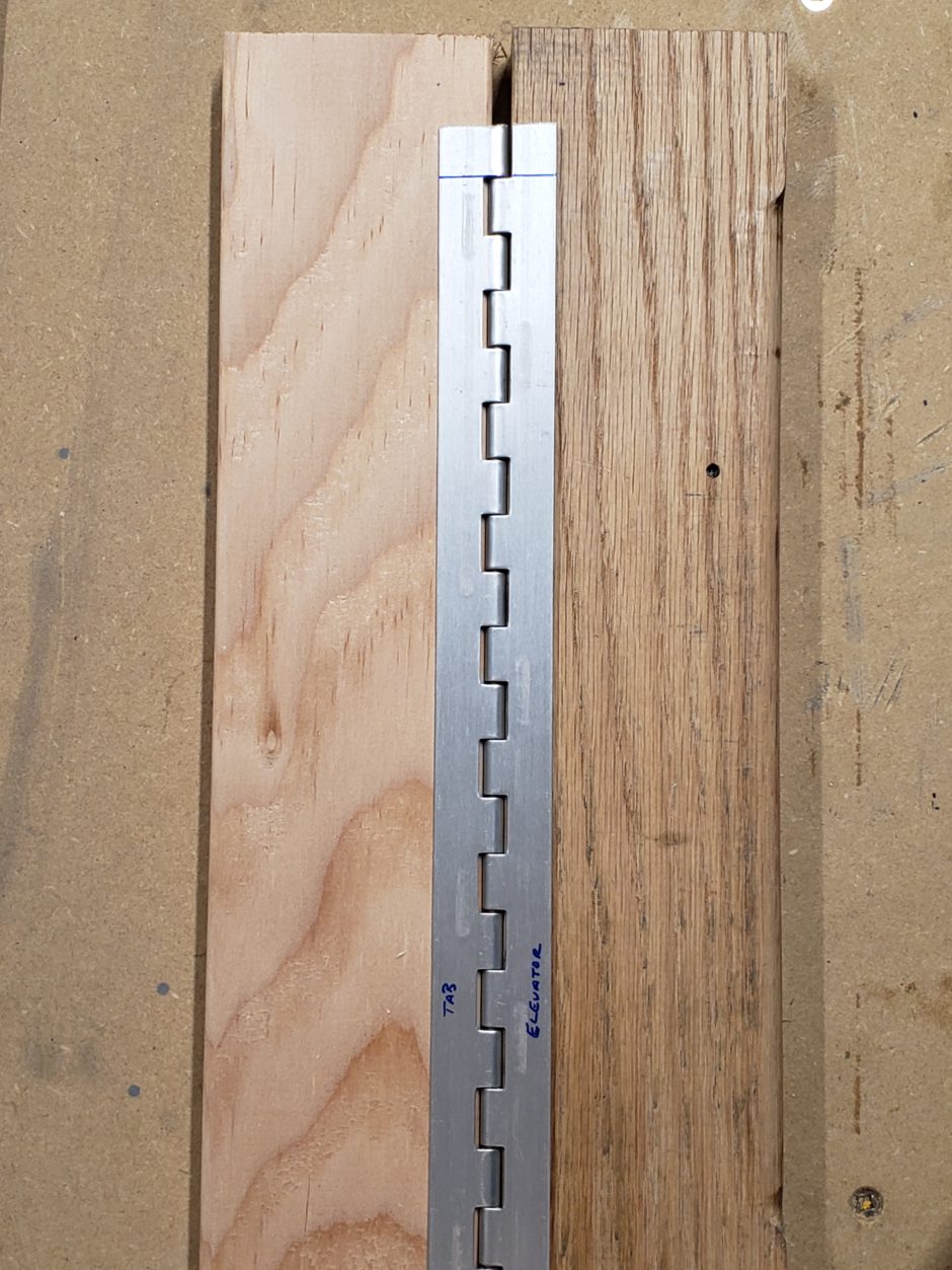
The first order of business is to cut the hinge to length. The goal here is to have the fixed hinge ears/loops/fingers on the outer ends that are on the elevator side. Some say that this doesn’t matter. All in all it’s what I went with.
The plans only give you 3 dimensions to work with to get the trim tab hinge in perfect alignment. Many of the build logs I reviewed, the only dimension that was really mentioned was the 3/32 inch gap. For me the starting point was the 3/8 dimension.
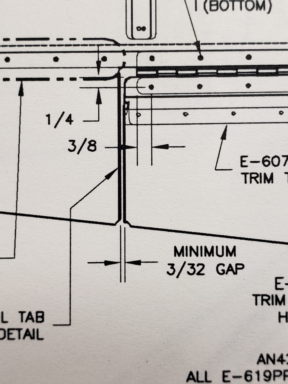
In the image below, I have the 3/8 inch edge distance layedout on the hinge. (The right most mark…I don’t know what I was doing with those other marks…?!?) Along the way, several build logs mentioned marking the center of the hinge flats with 3/16 inch edge distance. This worked well, and as you can see below, these lines are in place.
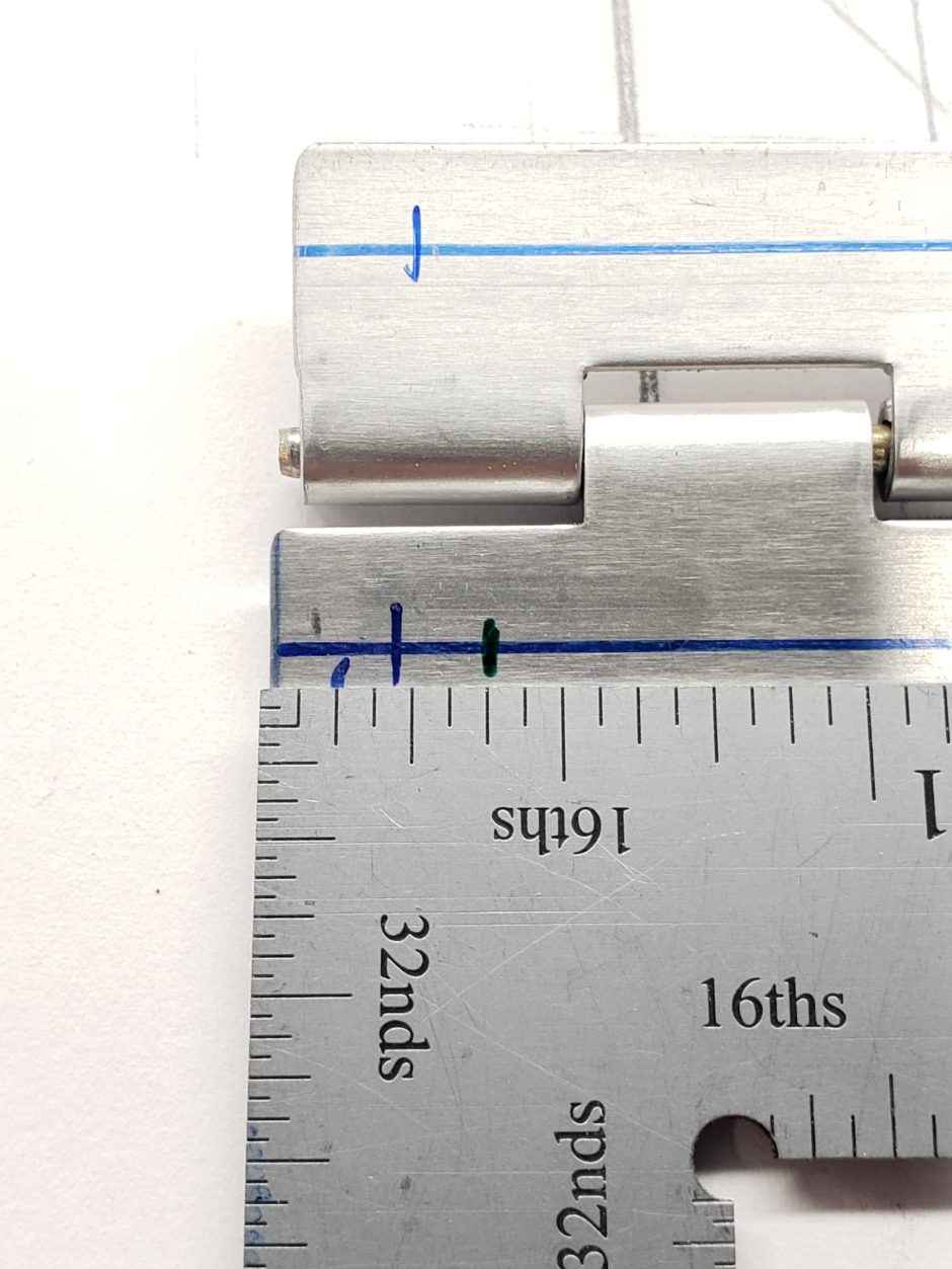
In the image below, you can see how I got the 3/8 in measurement aligned with the pre-drilled outboard hole on the trim tab.
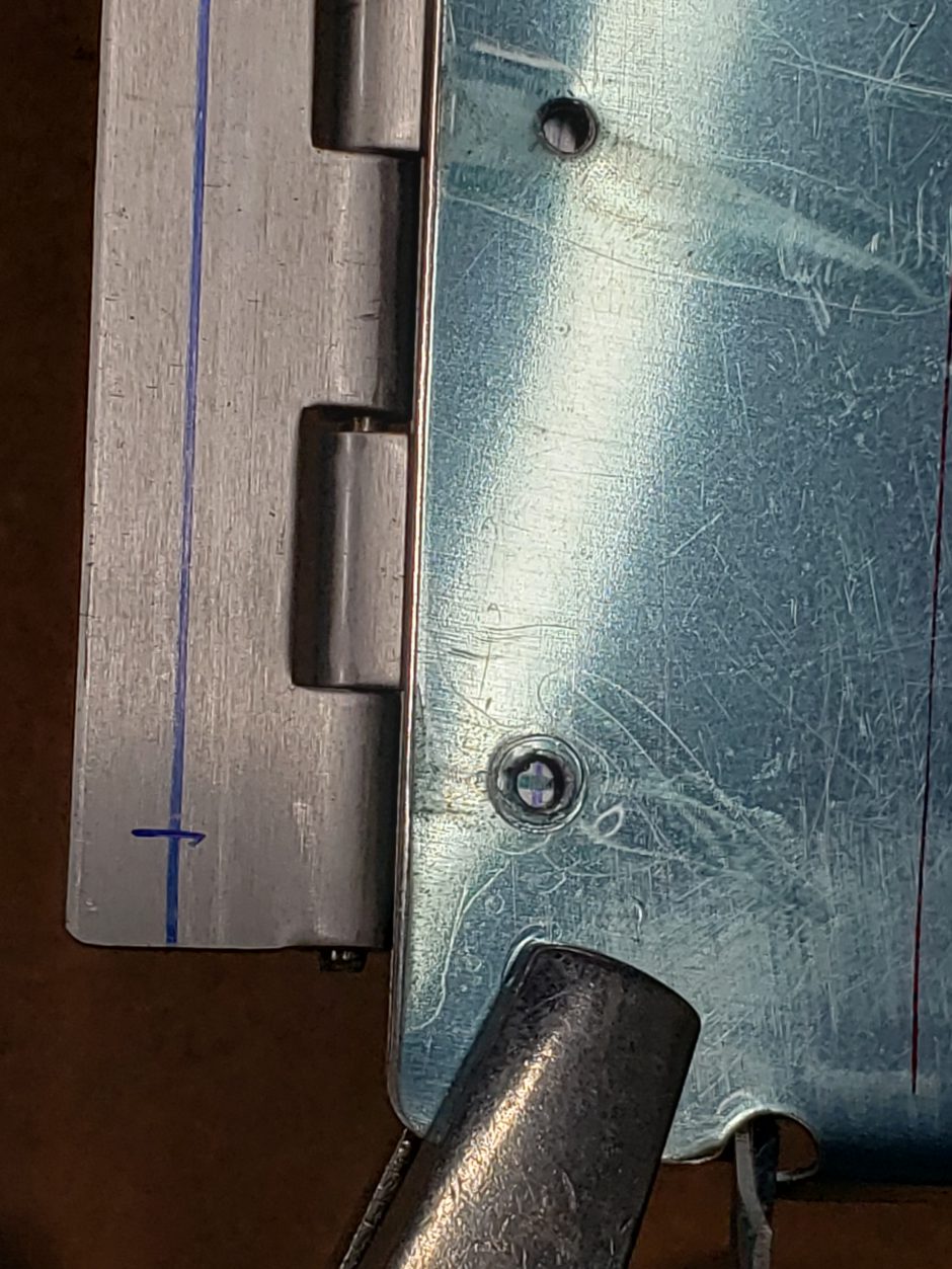
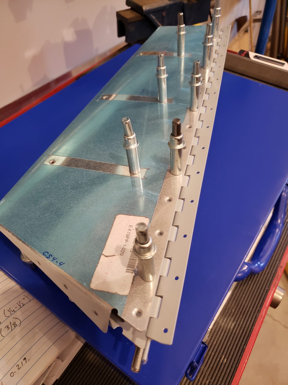
I then got the trim tab in place. This was a bit of tricky exercise. In the picture below you can see that I ended up clamping the hinge to both the trim tab and the elevator at the inboard end (there’s no where else to clamp this damn thing!). I worked the hinge spacing to get as close as I could to the 1/4 in. dimension shown in the plans. On the trailing edge side I used a 4 ft. level as a straight edge. I also pulled the hinge pin back a little on the inboard side, so that I could use a 90 deg. pick to hold up the hinge on the outboard side. I also used some scrap to give me approx. 3/32 inch spacing on the outboard side of the hinge.
After all this work, I was happy with the alignment, but wanted to make sure I wasn’t crazy. So I walked away for the night and revisited this the next day to confirm before I started drilling. (Measure twice…cut once).
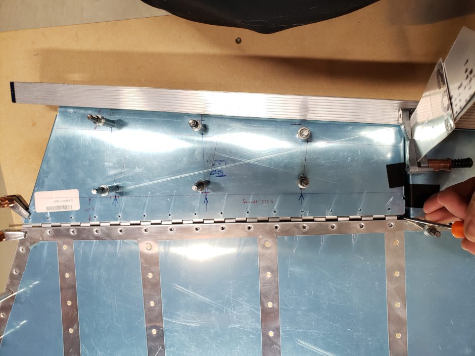
Upon returning the following day, I was still happy with the layout and measurements, so I proceeded to drill the first hole in the hinge. This was at the location of the 3/8 inch edge distance.
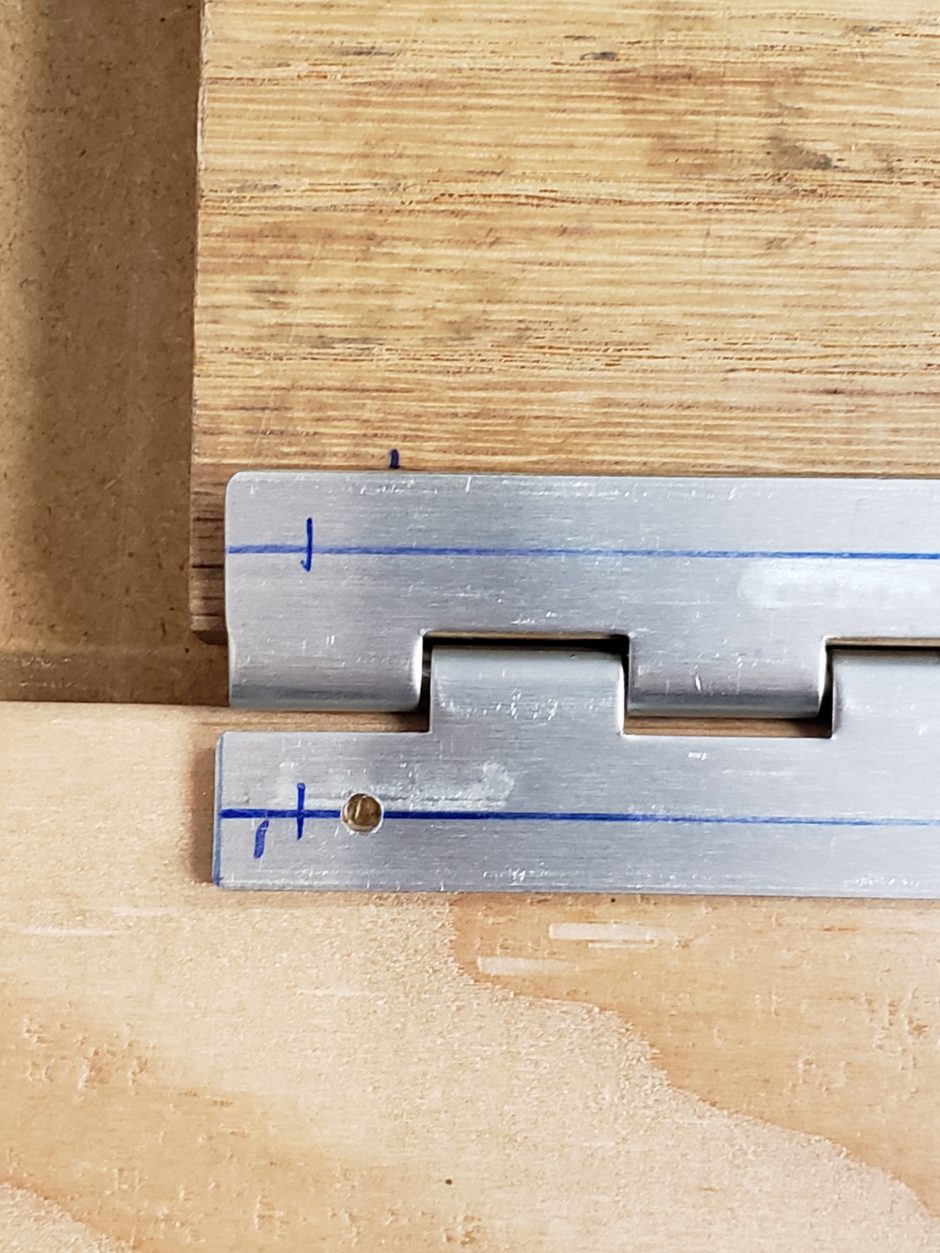
Now with the first of 3 given dimensions complete, the next step was to confirm that I had the 1/4 inch dimenion on the hinge set (before I start drilling anything). As shown below, the 3/16 lines drawn previously worked out perfectly, not only for acquiring the 1/4 dimension, but also for centerline hole spacing between the trim tab and elevator rivet holes.
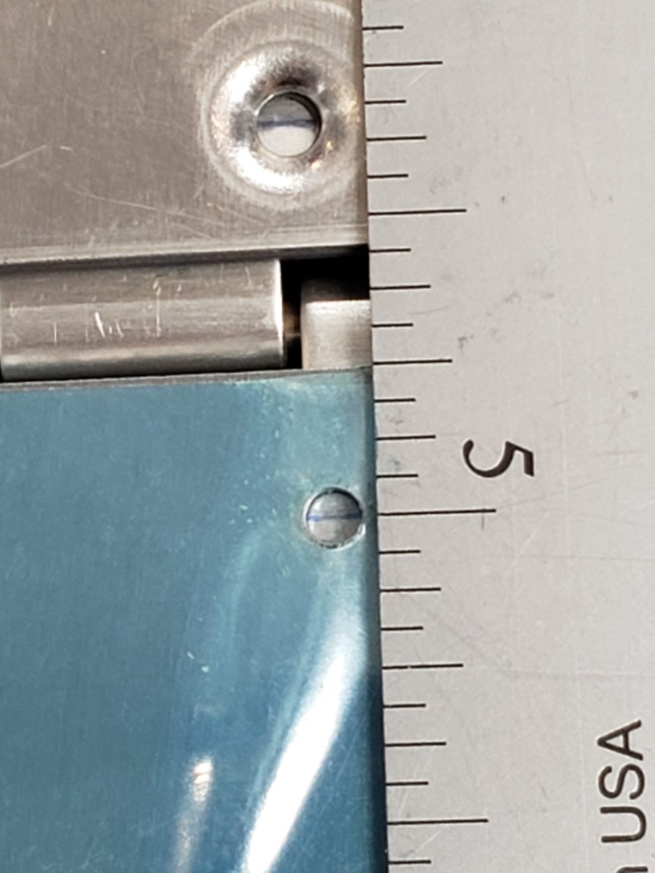
Finally, dial in the 3/32 inch gap distance between the outboard side of the trim tab and the elevator. Once that is set, and all other dimensions are still good. Drill the first hinge hole on the inboard side of elevator hinge.

Once the first two alignment holes are complete, recheck that everything else is still in alignment (straight edge along the trailing edge and inboard edges). I then proceeded to drill the length of the hinge.
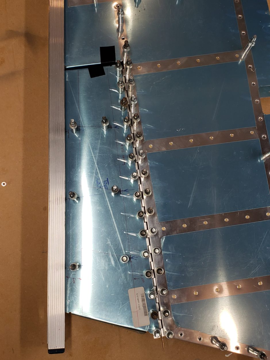
Trim Tab End Tabs
Now that the hinge was in place, the next step was to finish the pilot drilling on the Trim Tab – end tabs. The inboard side is straightforward as it comes pre-drilled.
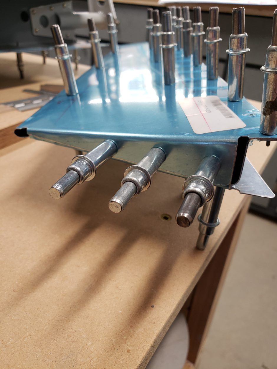
The outboard end was a bit more challenging. The key here is to ensure you have proper edge distance. As the tabs are quite small, you don’t have a lot of room to play with.
In the picture below, note that the top tab is larger than the tab below. I added the red line to identify where the edge of the bottom tab was. I then calculated by edge distances from that red line aft.

As shown in the image below, I kept these rivets close together. There is not a lot of room here to work with. After lots of measuring the only thing I felt comfortable with was sticking to the 2D spacing for these because if I went further aft I wouldn’t have had sufficient edge distance. Remember, with the overlapping tabs, there is lots of edge distances here to consider!!!
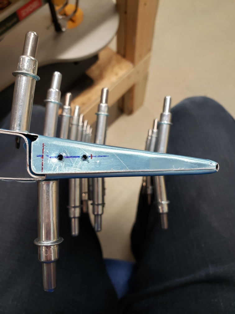
Left Elevator Closeout Tabs
After sorting out the trim tab tabs (there’s a mouthful) I then moved on to close out the tabs at the trim tab cutout on the elevator. These weren’t too bad to deal with. Again, Van’s doesn’t pre-punch these holes, probably because it’s impossible to know where they’ll end up after bending.
The instructions do make note to tell you to make sure the rivets from the trim tab do not interfere with the elevator skins. So I began by putting the trim tab in place and identified where the trim tab outboard tab rivet holes are located.
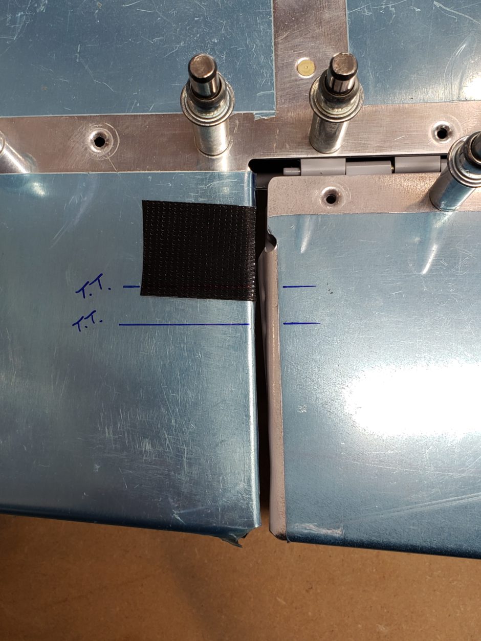
I then transferred these marks from the top surface down to the side of the tab, where I could again begin to figure out my rivet spacing and edge distance.
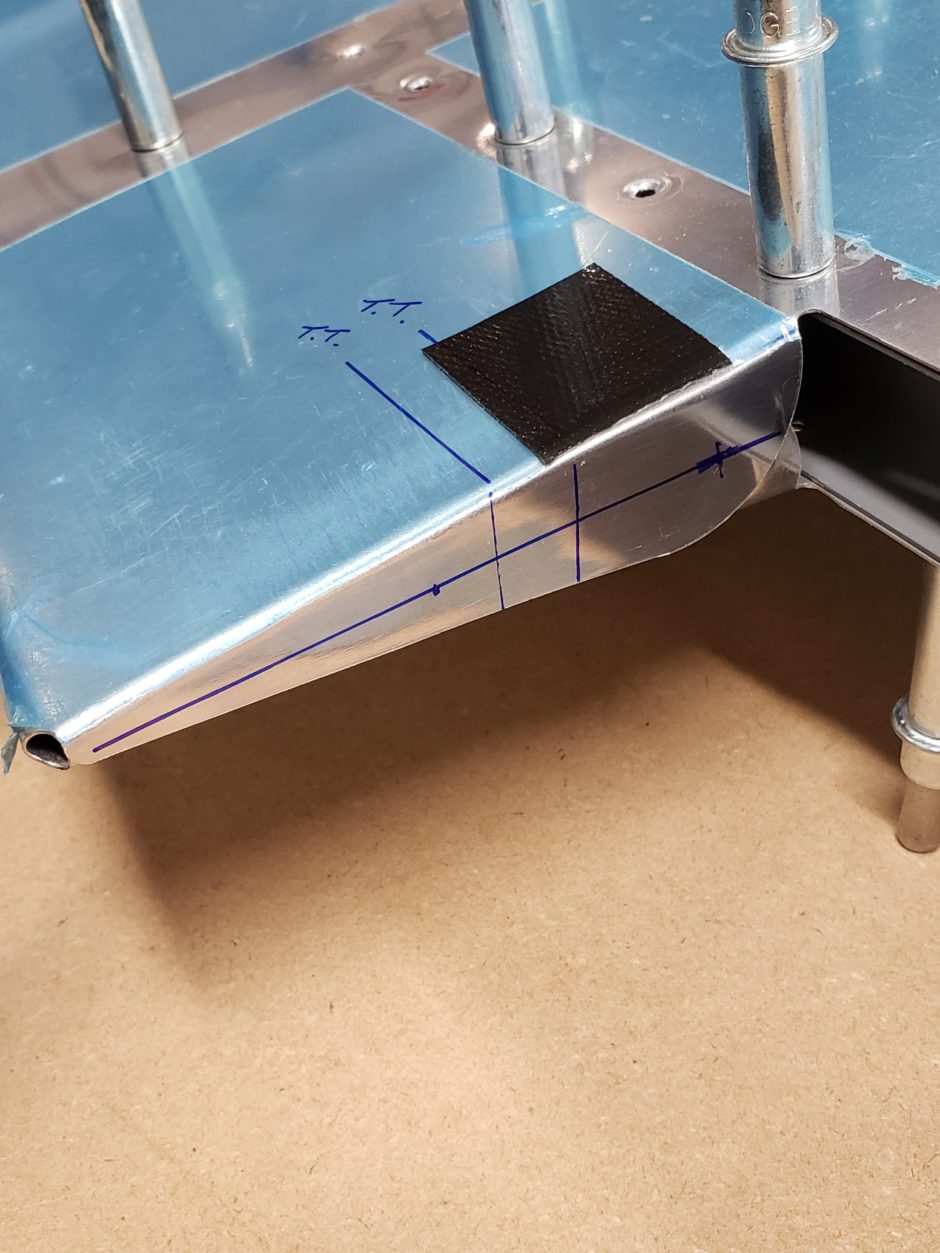
I then drilled these with a #40 pilot hole and then finished with #30 to fit the MSP-42 blind rivets. Some people have also used MK-319 rivets here so that they were flush. I may consider that when I get to riveting the elevator.
Trim Tab Prep
With all the layout and holes drilled in the trim tab and hinge, I then drilled all holes to the final #40 size (because I pilot drill at 3/32) then continued with all the usual surface prep and priming.
Another job done. The left elevator is now as far as I can go before the MD-RA pre-cover inspection (Canadian homebuilt aircraft regulatory requirment).
As always, please comment. I love to hear from my readers. Thanks again for coming along for this ride, you make my work worthwhile.
Leave a Reply