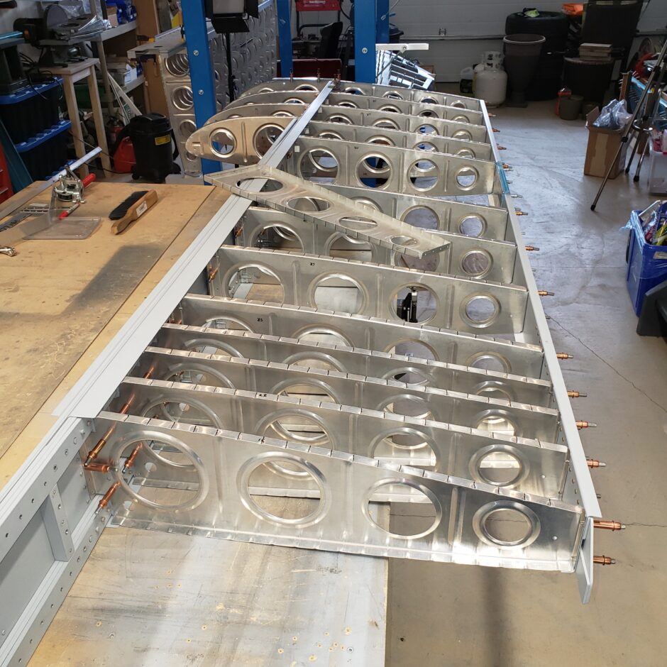
In today’s post, I’m getting back to the last rib to install in the wing, which is the aileron bellcrank rib.
The first thing you might notice is that the rib attach angle on the spar is facing the opposite direction. In this previous blog entry about the Left Wing Skeleton Build Up, I describe why my wing has ended up this way.
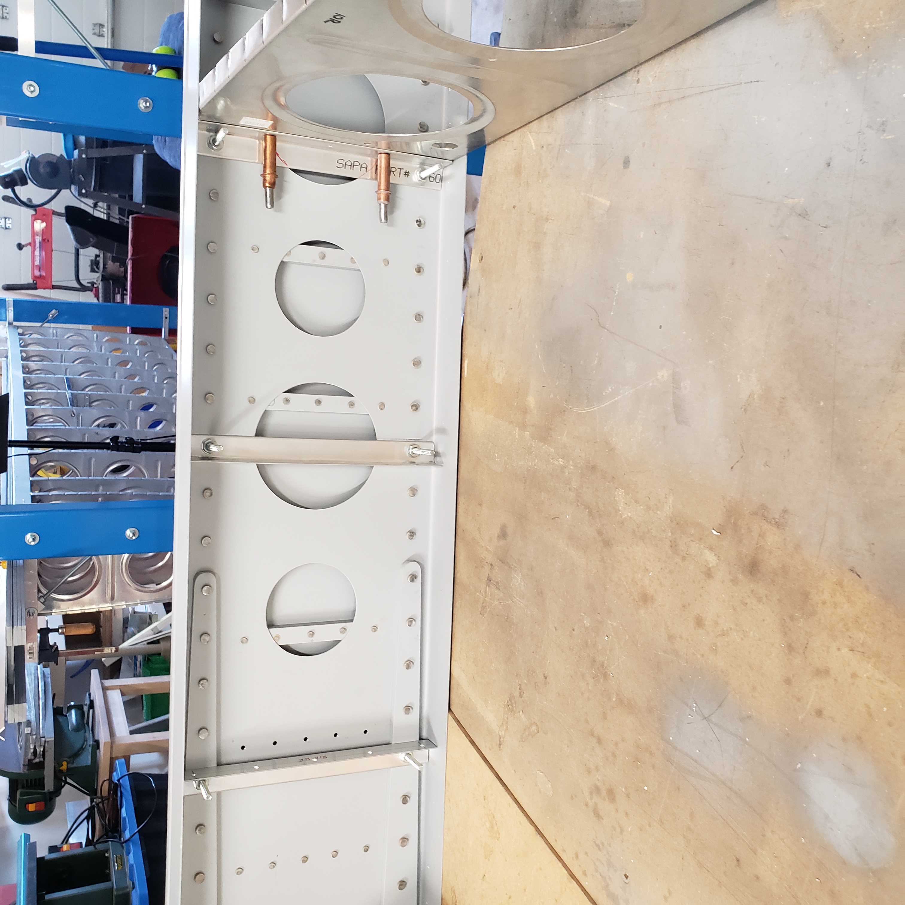
Because of the oopsie described above and for some other reason (which I cannot locate the previous blog entry for) I ended up cutting off the rear flange of this rib because it interfered with the rear spar doubler assembly.
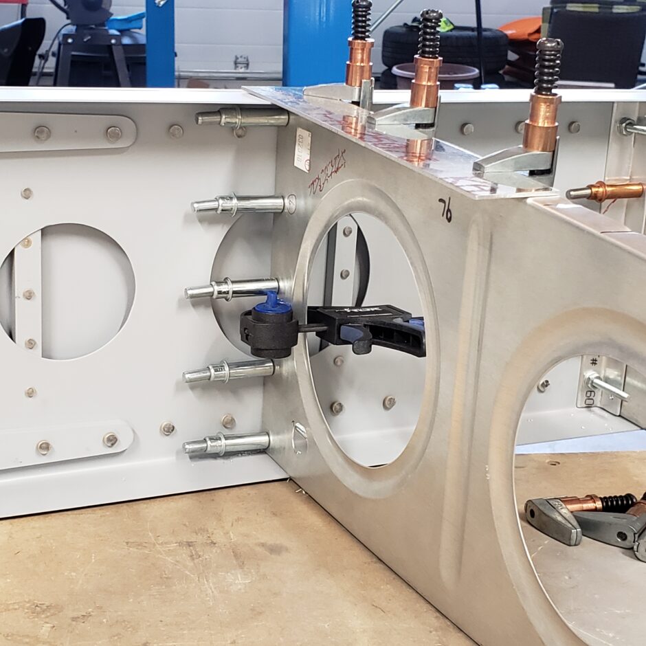
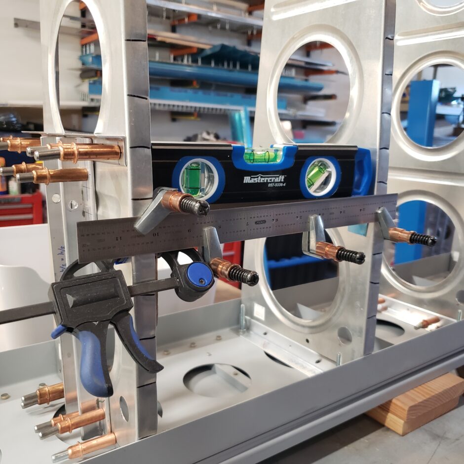
As you’ve seen so many times before, getting this rib in place and located is the same as all the other ribs up until this point. Get it all clamped in place, then you’re all set to drill the rib to the spar attach bracket, and in this case, if you measured out the rib spacing, you can also drill it to the rear spar.
Here’s another picture with everything all lined up, just before I drill the rib to the angle. For the drilling I used a long 12-inch # 40 bit.
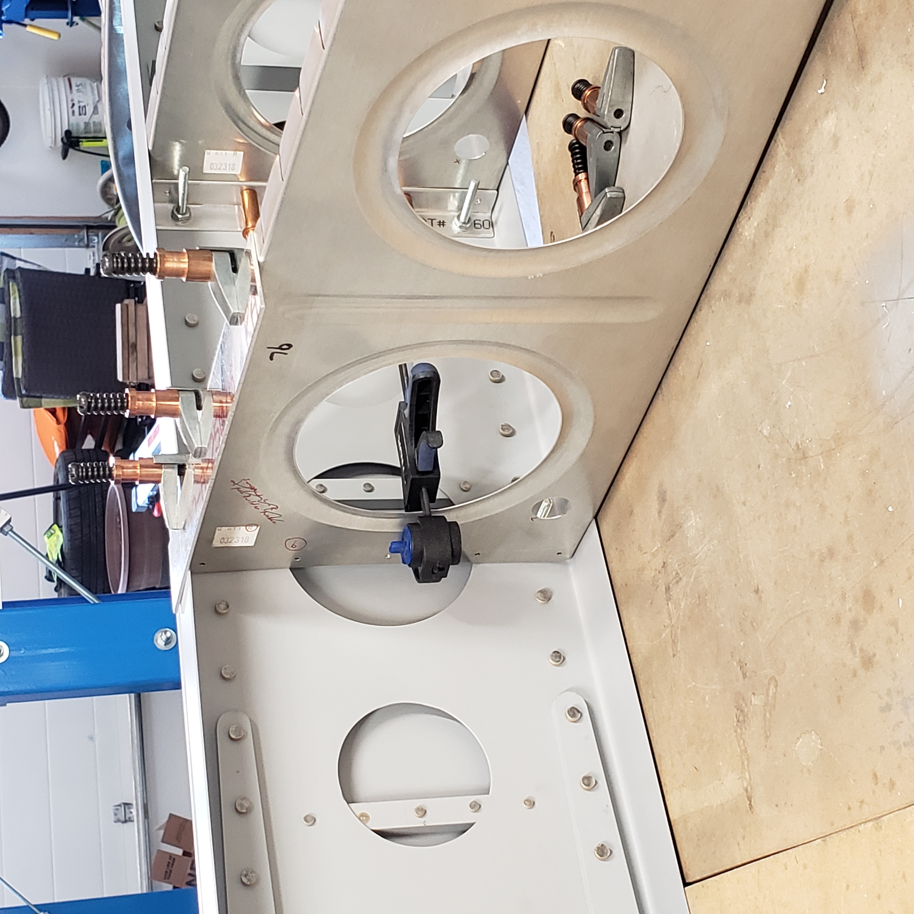
And just like that the # 9 rib is in place and located. You can see how I removed some of the adjacent ribs to be able to drill the rib to the angle.

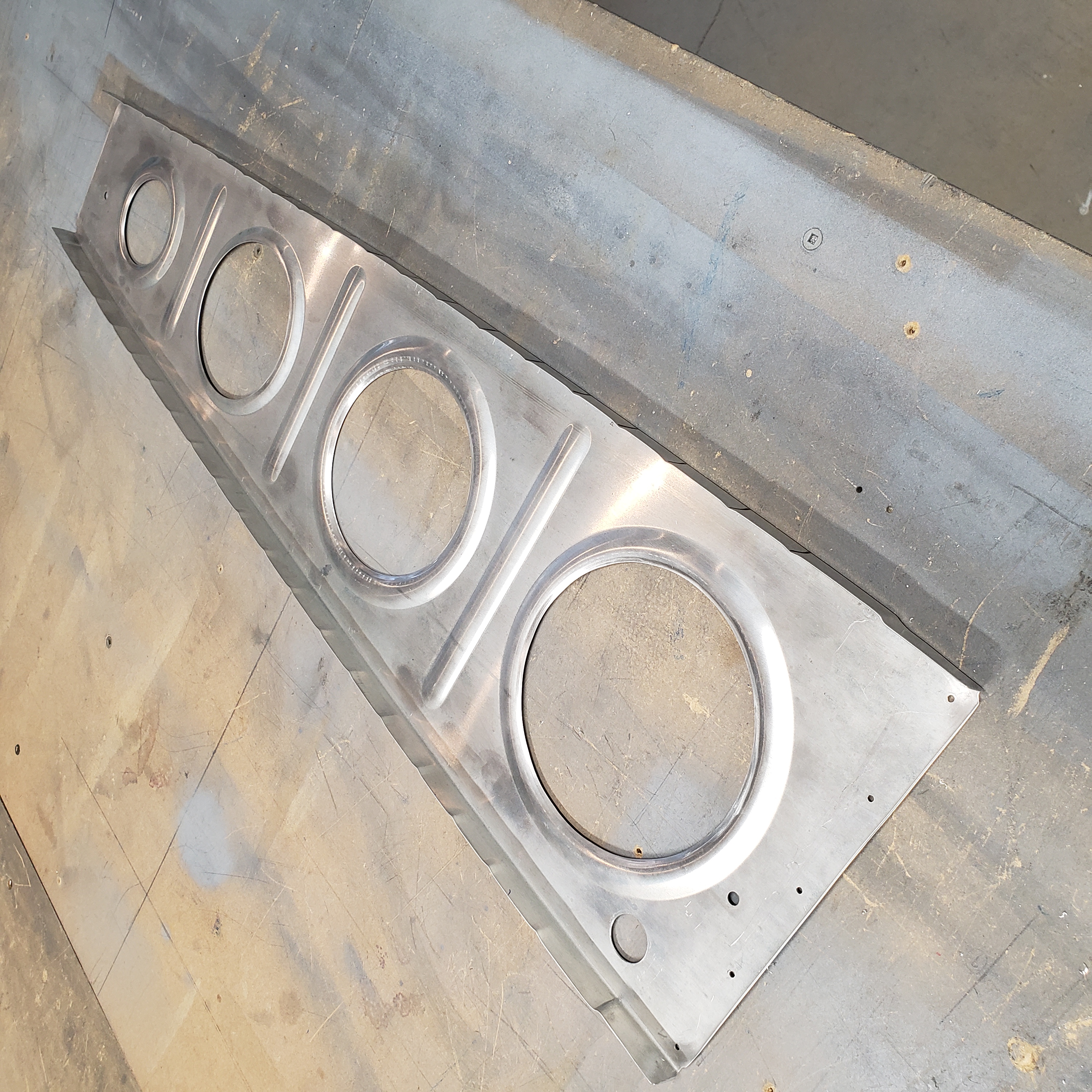
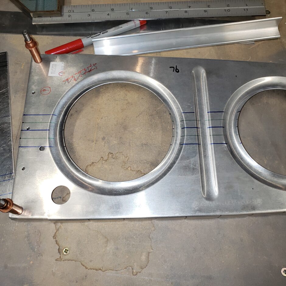
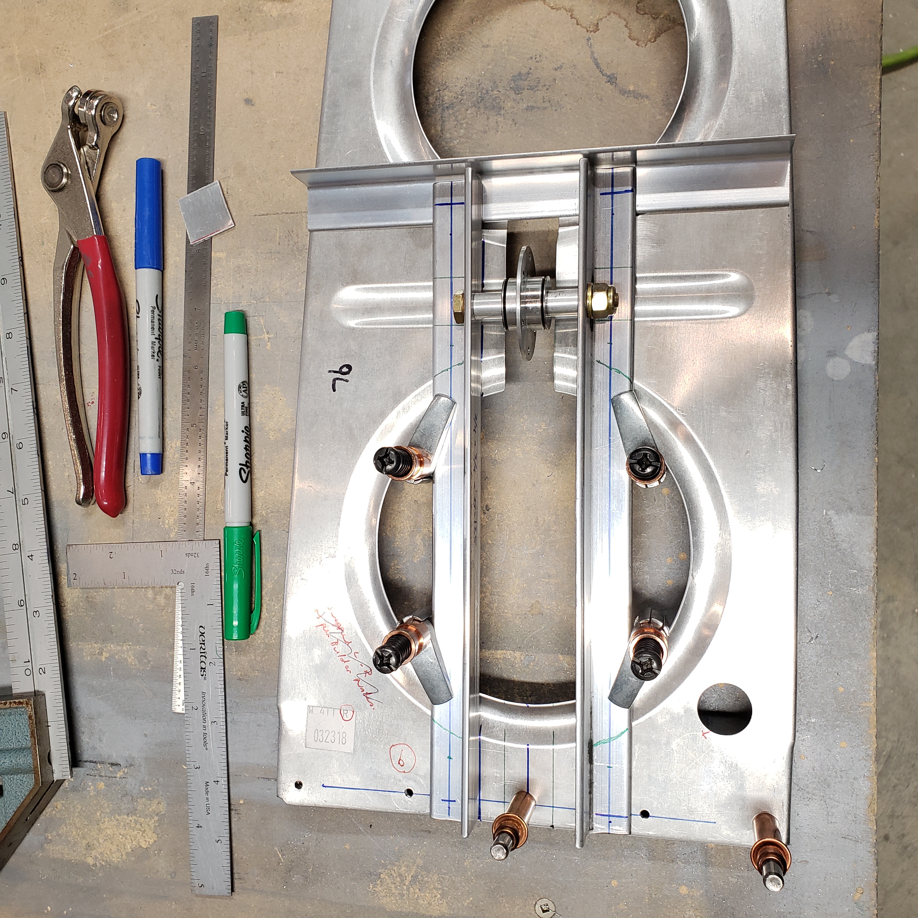
Next up was to do the layout of the bellcrank support angles on the rib, as well as to mark out the center strip of the rib that is cut out to make room for the bellcrank installation.

Here’s the rib with the bellcrank support angles marked. I also used some different colors to help keep me organized with what lines to cut and which ones to leave alone. This layout is pretty easy to do. The plans are very clear here in the way of instruction.
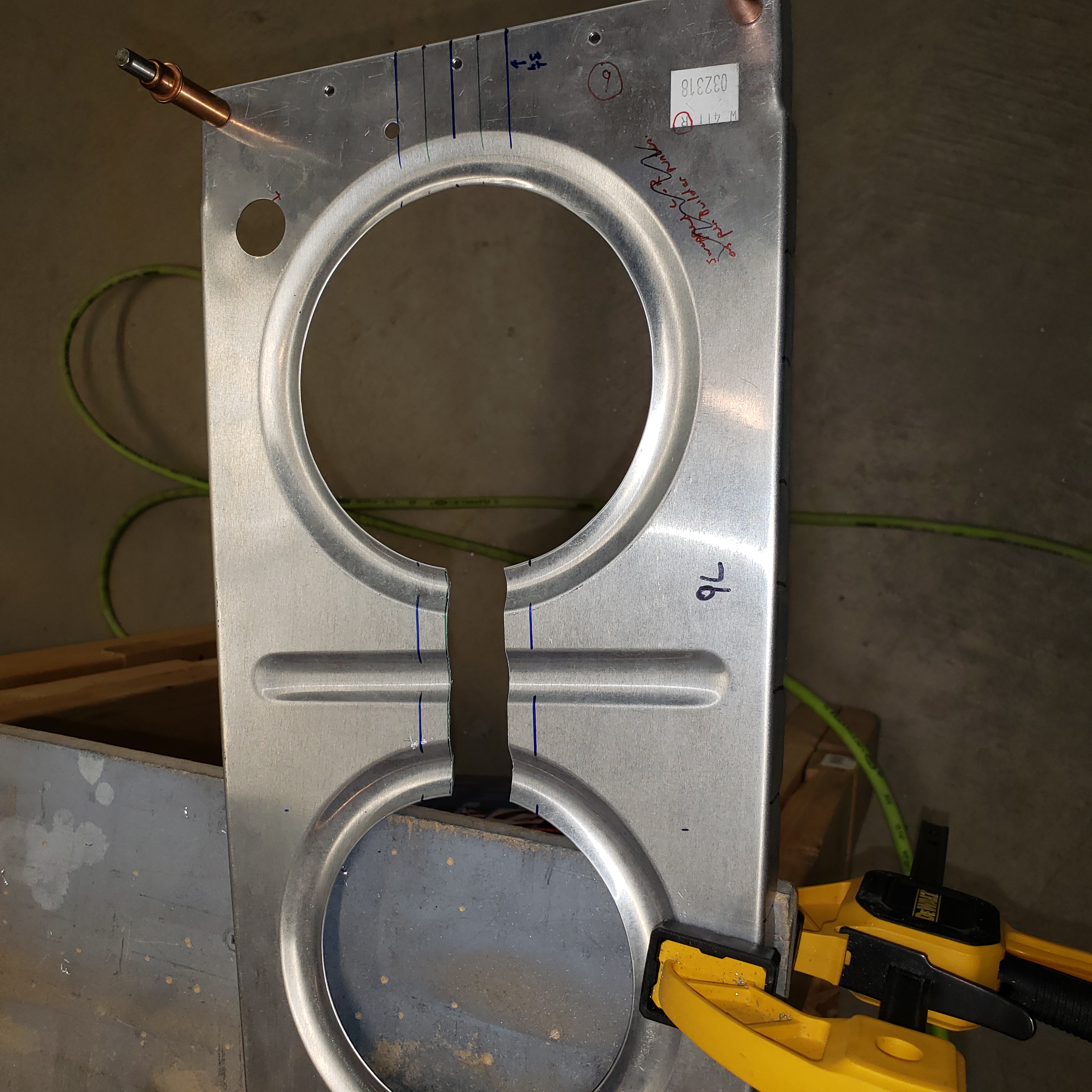
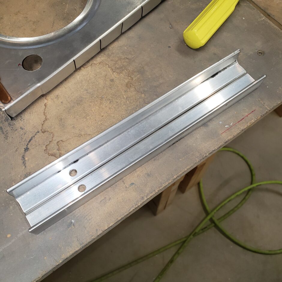
Here is the rib cut, for where the bellcrank is mounted. And the picture following is of the bellcrank mounting angles, which have been drilled for the bolt that mounts the bellcrank.
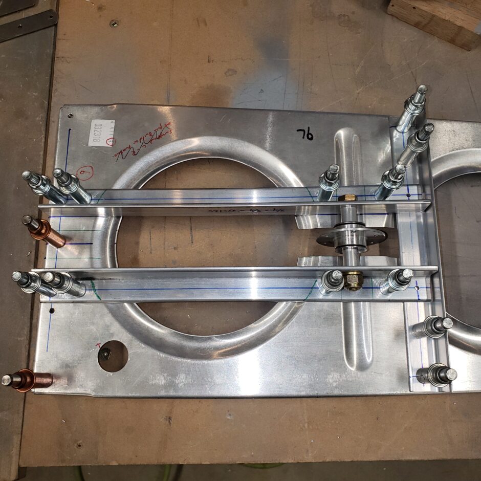
The next step was to start clamping all of the bellcrank support angles into place and to start marking them for where to drill the rivet holes.
I began drilling everything with a #40 pilot hole to start, then as shown in the next picture, all the holes are upsized to #30 for final assembly.
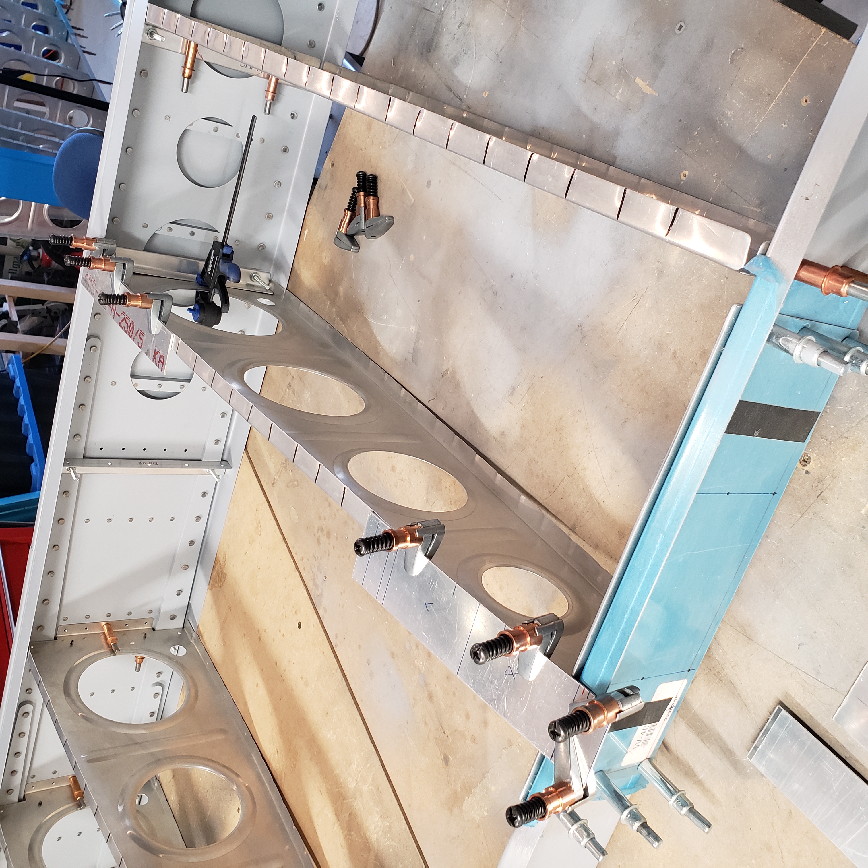
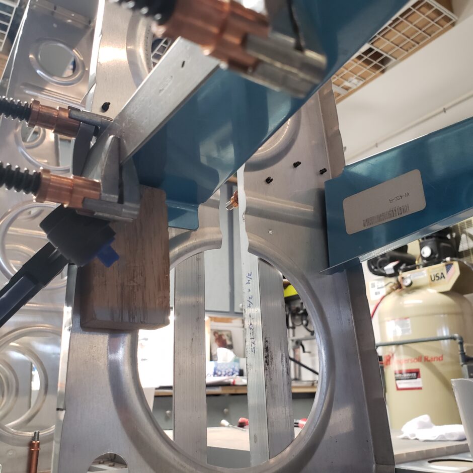
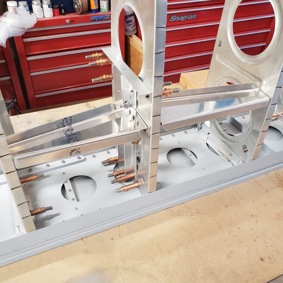
Moving on, I reinstalled the rib into the wing frame, and then started working on getting the spanwise support assemblies started. In the picture below, I’m working on the first of the 4 support pieces. Again, here you want to get your wing level, then work on getting the support piece level before you drill it to anything. You can’t see the support piece in this picture, but its in there.
Here’s another angle of how I’ve got it clamped tight and level.

And here’s a shot from the underside.
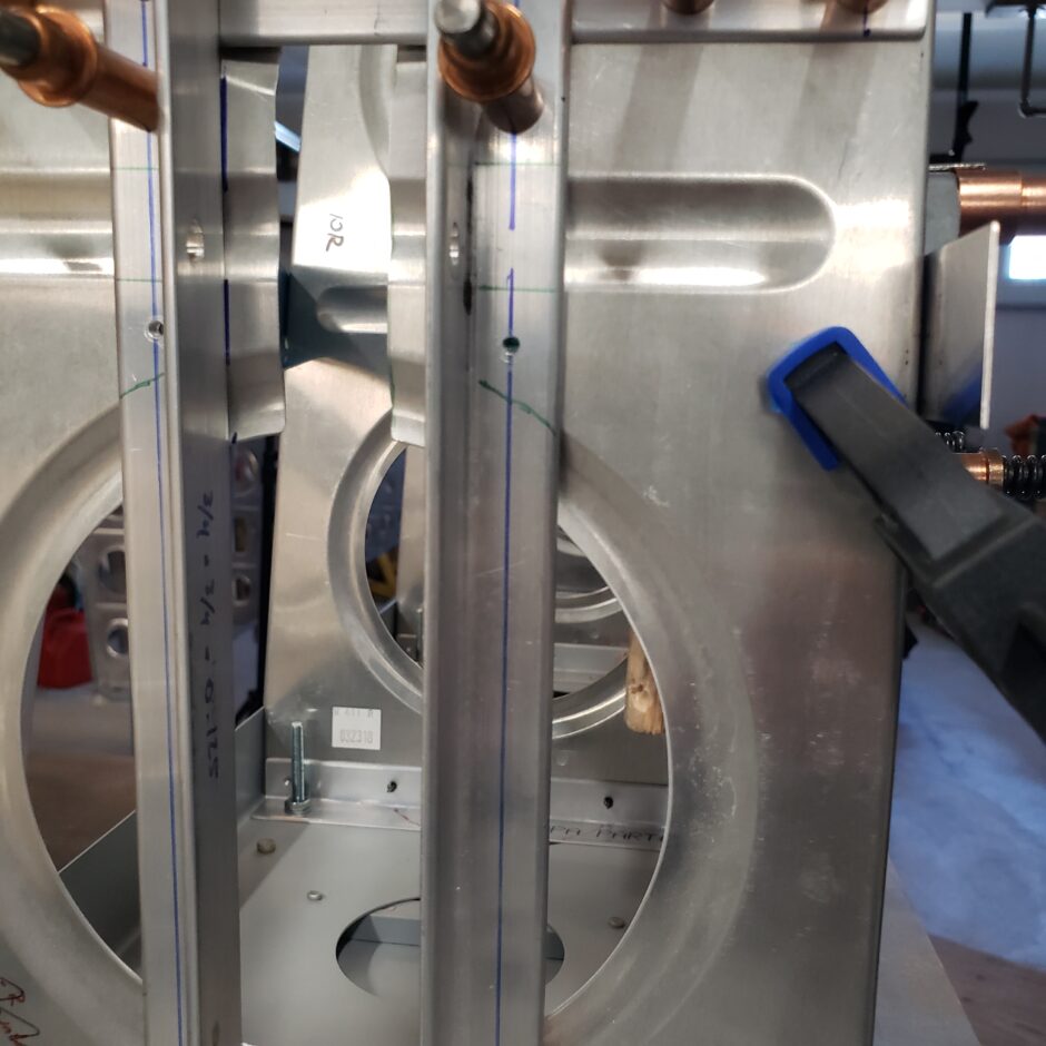
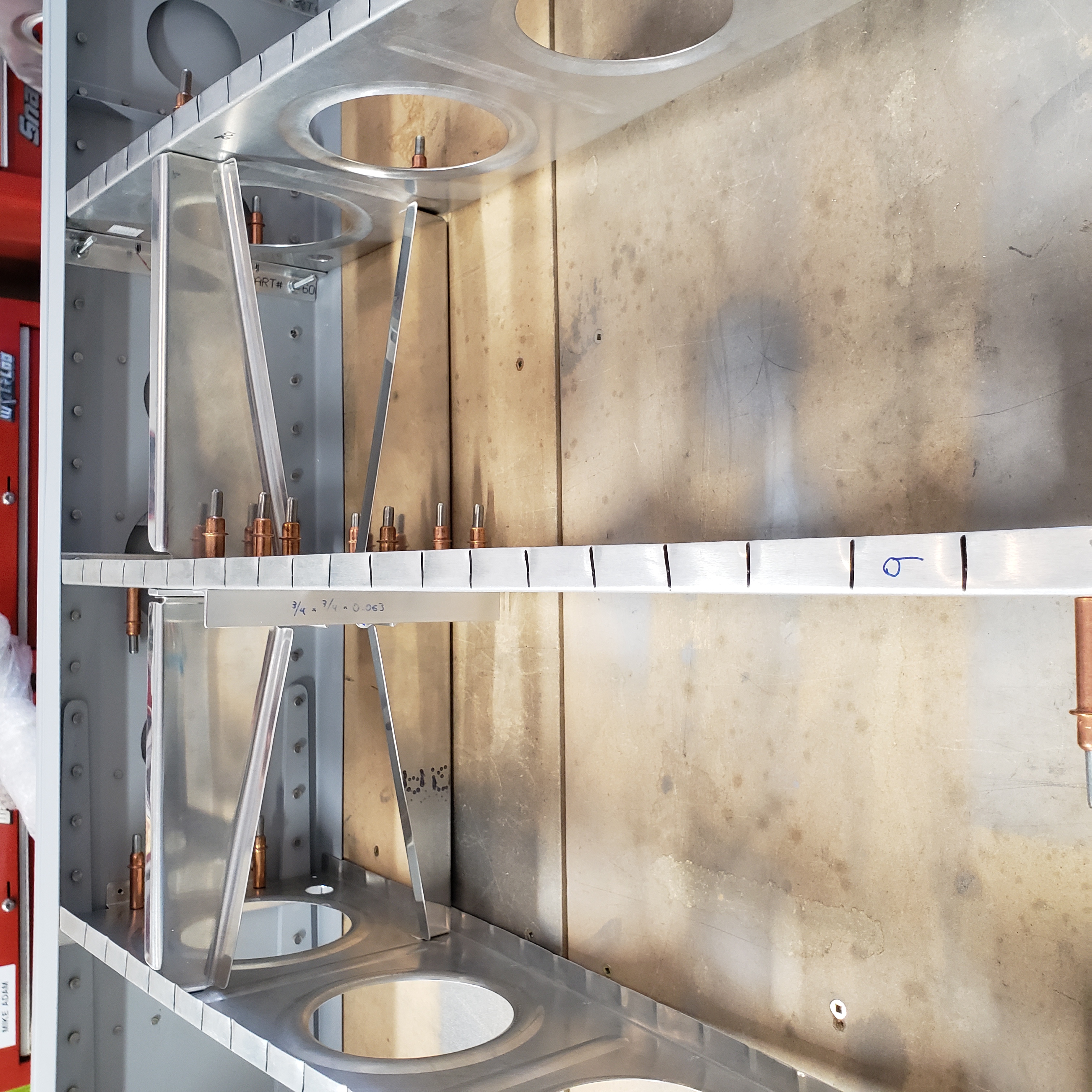
In the picture below, this is a picture taken from the inboard side of the #9 rib, and just to the left of the blue clamp, you can see a drilled hole. This is the first hole to match drill on the angle. Then you can work towards the right, adding 2 more holes to hold the support bracket in place.
After drilling the first hole, I then removed the support piece to layout and pre-drill the other 2 holes.
With the 2 other holes predrilled, it was easy to align the holes on a line I drew on the rib. Just align the holes with the line and you’re located. Simple. Once the one side was on, I could then quickly proceed on getting the next (opposite) support piece in place. I say it’s easy and it probably looks like this went quickly, however don’t be fooled…this is a pretty slow and tedious process. Not difficult, just slow.
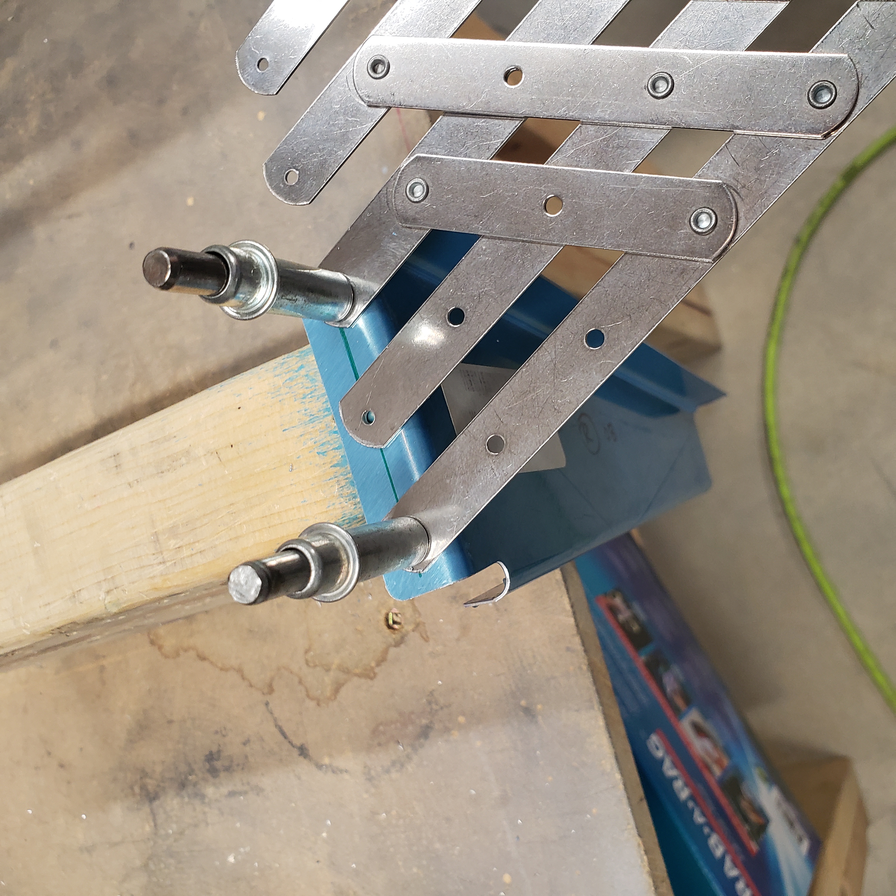
Also, when matching up the two sides of the support angles, I found it to work well by clamping the parts together on the common flanges, and then also clamping them to a piece of angle, which helped keep them straight, sort of like using a false skin. This helped in being able to match drill the common flanges, again with a long drill bit.

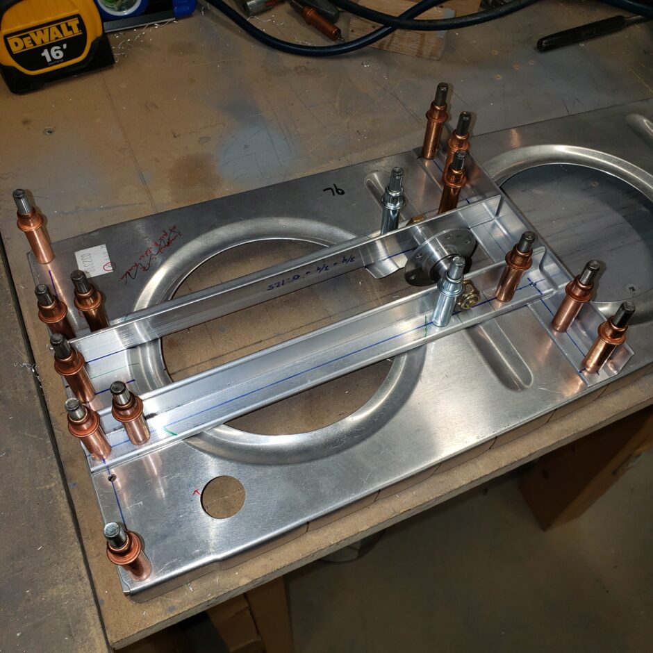
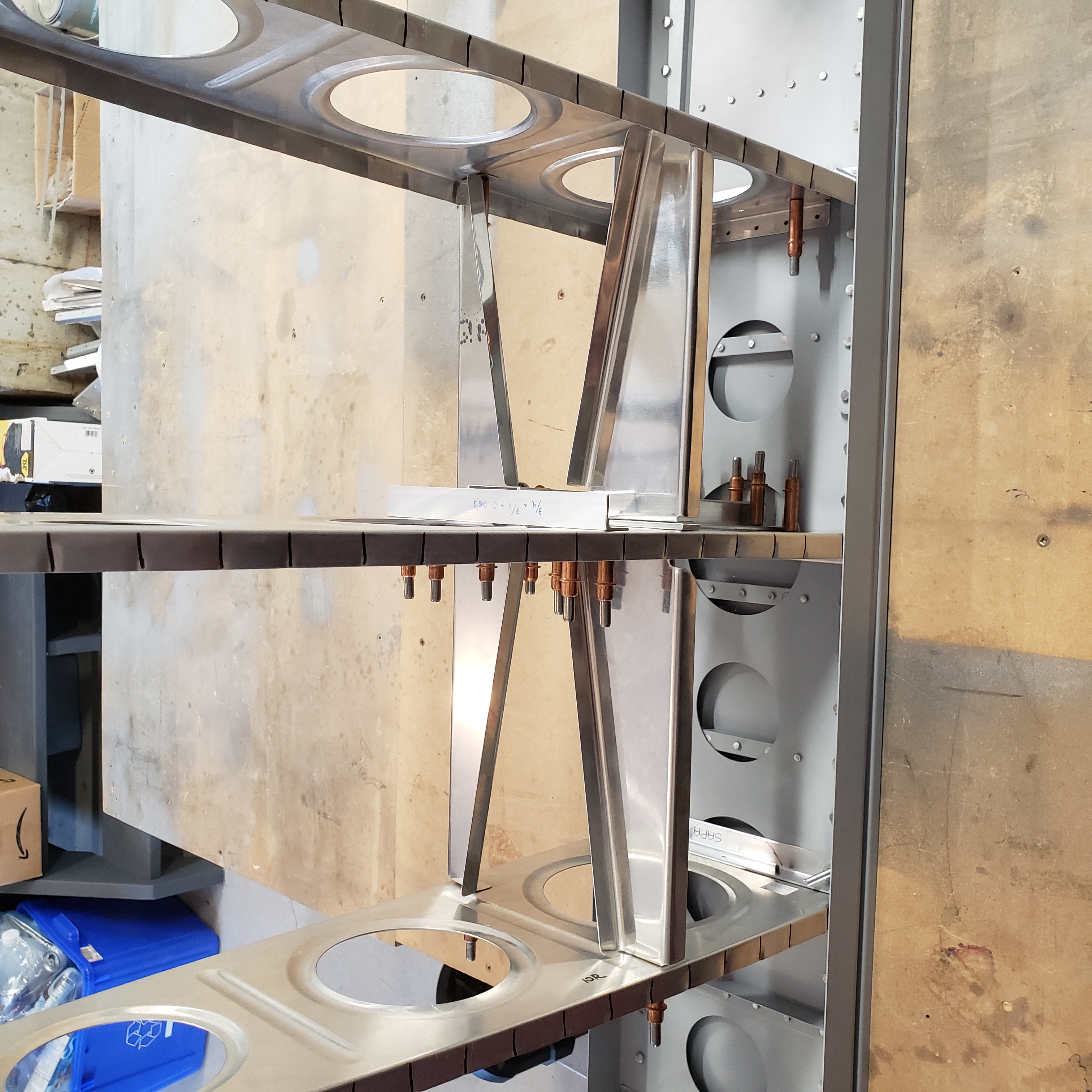
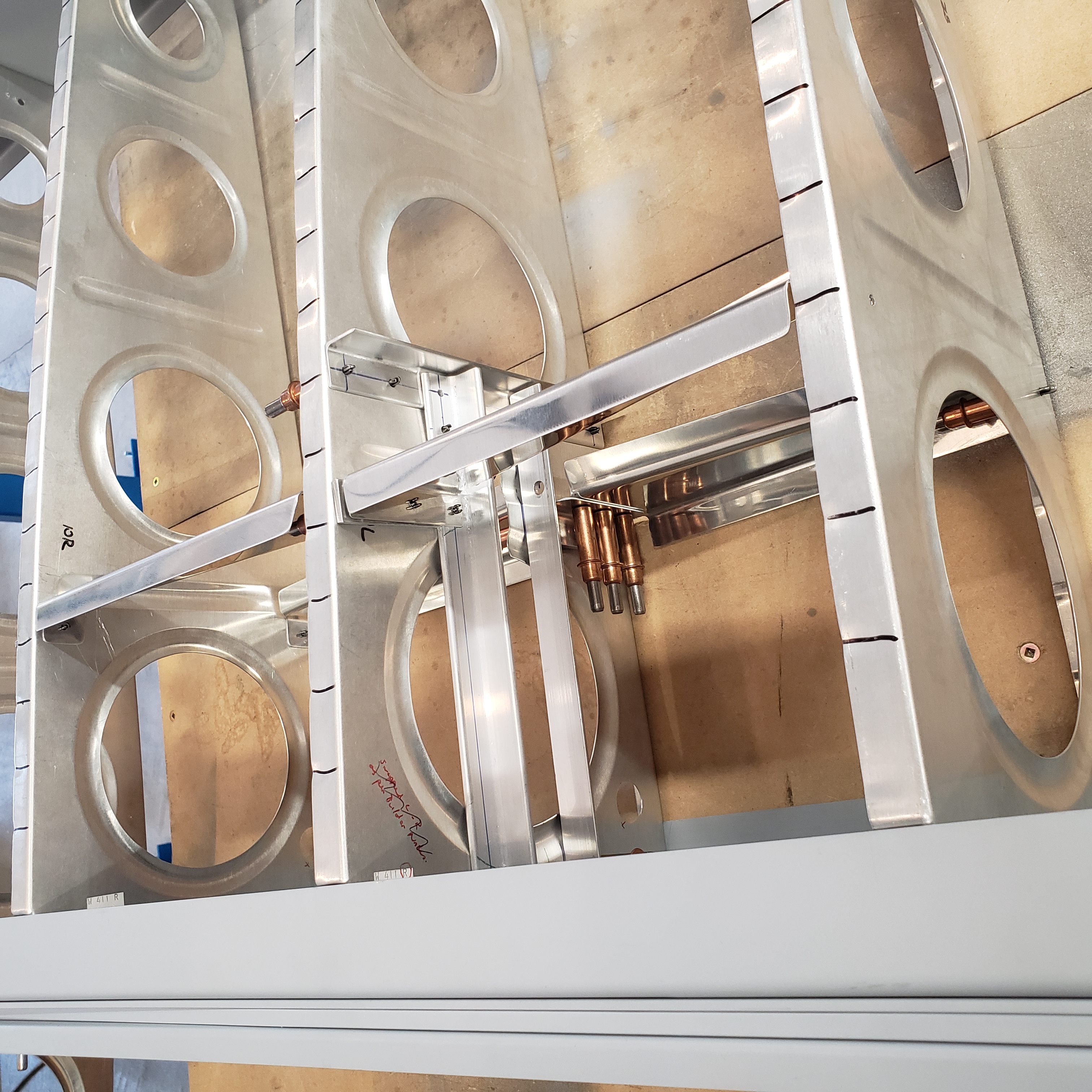
Here is a shot of all 4 of the bellcrank support pieces in place.
I’m skipping over some of the details of the process because I’ve previous documented this process in an earlier blog when I built up the left wing. If you have questions about this, please comment below and can help clarify it for you.
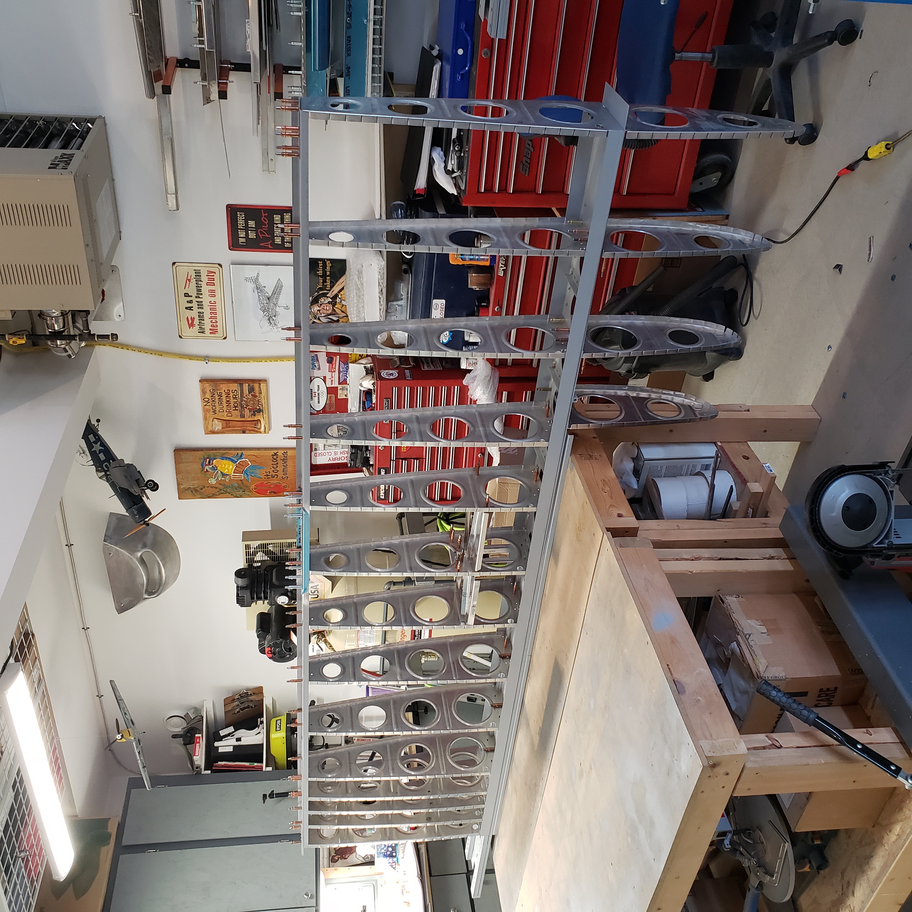
The following pictures are just some more pictures during this process.

That’s all for today folks! Please comment. I love to hear from my readers. Thanks again for coming along for this ride, you make my work worthwhile.
Good day!
Leave a Reply